Contents
Pin Description of ISD1820 Recorder Module
We included a pinout description of the ISD1820 board:
| Pin Name | Pin Description |
| VCC | 2.4 – 5.5V |
| GND | Ground |
| FT (FeedThrough) | The microphone drives the speaker via FT mode. |
| REC/REC (Button) | Both SP+ and SP- pins drive the loudspeakers with 8 ohms impedances. |
| P-E/PLAY-E (Button) (Playback, Edge-activated) | This detects a HIGH-going transition, and it will continue until it reaches the end of memory space or an End of Message marker. Activating the PE jumper will set the playback to endless loop mode. |
| P-L/PLAY-L (Button) (Playback, level-activated) | The input pin level will activate a playback cycle when it changes from LOW to HIGH. |
| SPI (SP+ and SP-) | Both SP+ and SP- pins drive the loudspeakers with 8Ohms impedances. |
| MIC (Microphone In) | The microphone input transmits signals to the chip amplifier. |
Features of isd1820

(The ISD1820 board allows you to record audio for 20 seconds.)
You can also check out some of the features below:
- Voltage operating range: 2.4V to 5.5V DC
- Drives 8 Ohms 0.5W speakers via the audio amplifier
- Equipped with an on-board microphone
- Dual operating modes: Standalone mode and microcontroller-driven mode
- Automatic power-down mode (standby mode)
- Can record 20 seconds of audio
- Push buttons for playback.
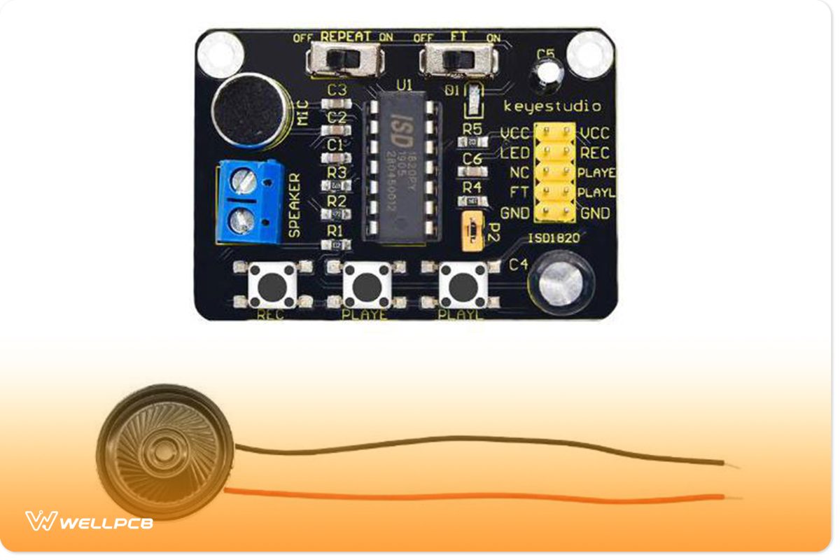
ISD1820 Recorder/Playback Module

(An example image of the ISD1820 module board.)
The ISD1820 board serves as a Voice Recorder and Playback module. It offers multi-segment recording capabilities. Additionally, users can record audio by adjusting the resistor. Overall, this module features Flash memory. In that case, it stores data for 100 years. Even so, you can record/erase messages for a very long time. That’s because the life cycle lasts up to 100,000 years. Overall, this voice recorder module provides decent sound quality.
Applications

(You can utilize the ISD1820 as a voice recorder.)
Some potential applications for the ISD1820 voice recorder include:
- Security System
- Voice recorder
- Accident voice recordings
- Collision message recorder
- Audio playback on a microcontroller
Circuit Projects With the ISD1820
We also described three circuit projects involving the ISD1820 board.
Car Accident Detection System

(Circuit diagram of a car accident detection system.)
If you ever find yourself in a car accident, you can relay a voice message to someone far away. That way, you can tell them where the accident occurred. This circuit relies on a FlexiForce sensor, also called the force-sensitive resistor. As illustrated, the uppermost FlexiForce sensor’s lead connects to Arduino’s 5V pin. Meanwhile, the FlexiForce sensor’s 1st lead connects to the 10k resistor. Next, a wire runs from the FlexiForce sensor’s middle section and links to the analog pin A0 along with a 10k resistor. Finally, a 47uF capacitor forms a connection in parallel with the 10k resistor.
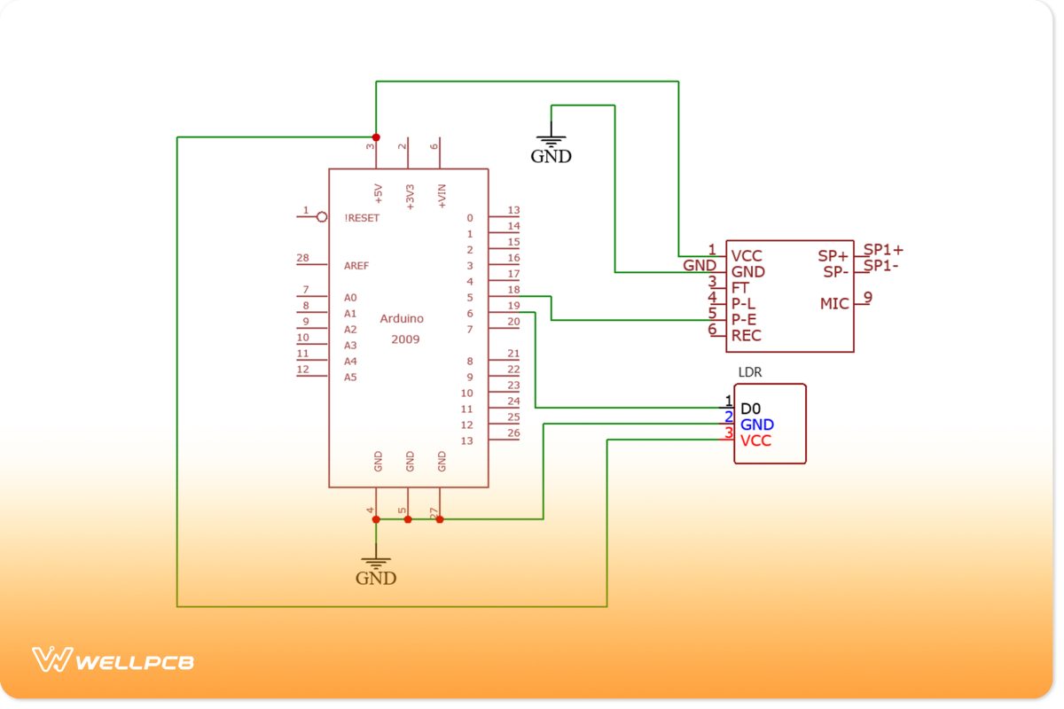
Arduino ISD1820 Security System

(Arduino ISD1820 security system circuit diagram.)
An LDR module connects to the Arduino board. In this case, the LDR’s VCC and GND pins connect to Arduino’s 5V and ground. Meanwhile, the LDR’s D0 pin forms a connection with pin six on Arduino. You can adjust the LDR via the variable resistor. The project features a laser module, which sits in front of the LDR. So, blocking off this light will prevent it from reaching the LDR. Therefore, this will trigger the microcontroller to play the recording.
Door Opening Voice Message System

(Door opening voice message system circuit diagram.)
You can install this circuit in various locations, including offices, malls, shops, etc. It generally plays several voice-recording messages as needed whenever someone enters the room. Also, you can utilize it to play a break time message for a worker.
Source: Wikimedia Commons
The circuit features a Reed switch sensor that connects in series with the 10k resistor. Once a door closes, the GND will connect with Arduino’s pin 6. After the door opens, 5 volts will connect to Arduino’s pin 6.
Summary
Overall, the ISD1820 voice recorder module presents excellent capabilities. It generally allows you to record a 20-second voice message. In that case, you can install it in your store to automatically welcome customers. However, these applications may require particular components. You also won’t need to worry about the data’s life cycle. That’s because the ISD1820 features a flash memory that stores audio for up to 100 years. So you can keep running the same message forever if you choose.
Do you have any questions regarding the ISD1820 module? Feel free to contact us!


