Contents
What is uln2003?
ULN2003 integrated circuits are high current, high voltage Darlington arrays that give a raised current gain than any single transistor. They also contain seven Darlington pairs (open collectors) with suppression diodes and standard emitters.
A simple circuit diagram explaining how transient-voltage-suppression diodes work
Note: One Darlington transistor pair equals two bipolar transistors with maximum operating values of 500mA (max 600mA) and 50V.
You can commonly find it in 16-pin plastic DIP packages. The packaging further has a copper lead frame that lessens thermal resistance.
uln2003 Pin Configuration
ULN2003 pinout
The Uln2003 has a total of sixteen pins, as we’ll discuss below;
- Pin1 to pin7/ Input1 to input7 – They are the seven input pins of the Darlington pair. Further, a +5V triggers each of the pins while being connected to the transistor base.
- Pin8/ common ground pin – It provides a ground reference voltage often at 0V.
- Pin9/ COM pin – It functions as the voltage test or suppressor pin. However, using it is optional.
- Pin10 to pin16 (Output pin 1 to output pin 7) – They are the common ground in a ULN2003 IC. Furthermore, respectively represent the output pins of the seven input pins. Also, connecting the output pins to the ground occurs when there’s a high voltage (+5V) in the input pins.
Uln2003 Pinout: uln2003 Features
The features and specifications of ULN2003 IC are as follows;
- First, it comprises seven high current and high voltage Darlington pairs.
- Then, each of the pairs has a rating of 500mA and 50V. Additionally, it can come with a different version having a voltage range of 100V.
- Thirdly, you can use logic devices such as PIC, Arduino, Digital gates, and others to control the IC directly.
PIC microcontroller
Source; Wikipedia
- It has a pin that helps with inductive load driving and an internal flyback system protection. Mostly, you’ll pin the inputs opposite the IC output to abridge the board layout.
- Also, you can collectively connect the seven output pins to drive loads of approximately ~3.5A (500mA × 7).
- Moreover, you can protect ULN2003 IC from back EMF protection using its inbuilt internal clamp diode.
- A +5V power supply can trigger the input pins.
- Finally, it is available in 16-pin TSSOP, PDIP, SOIC, and DIP-packages. Besides, its output matches with all 5-V CMOS devices and TTL logic.

(an example of a TSSOP package)
Example ULN2003 Circuits
The circuit examples below show how ULN2003 IC works.
Uln2003 Pinout: Arduino DC stepper motor driver circuit
The first circuit illustrates how to use Arduino through ULN2003 IC to operate the DC stepper motor.
Uln2003 Pinout: PIC Microcontroller 5 Relay Driver circuit
Our second example circuit incorporates ULN2003 IC, which helps the PIC microcontroller drive the 12V relay driver circuit.
Uln2003 Pinout: Stepper motor driver using a parallel port
The last circuit is the easiest of the three in construction. It allows you to use your computer’s parallel port to regulate a unipolar stepper motor.
Circuit of a stepper motor driver using a parallel port
Consequently, you can use the stepper motor in other engineering projects like constructing gadgets, e.g., PCB drilling mill, elevator, etc.
Uln2003 Pinout: ULN2003 Applications
Uln2003 IC has a wide range of countless applications. Some include;
- In driving current stepper motors,

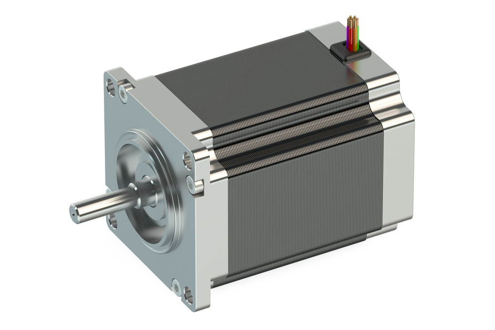
(stepper motor)
- As a touch sensor with Arduino microcontrollers,
- In driving high current loads while using digital logic circuits,
- As logic buffers in digital electronics,
- In driving relay modules (up to seven relays) or circuits for relays,
- In driving high-current LED bulbs.
Conclusion
To summarize, ULN2003 IC is a driver relay suitable for operating several relays, such as relays DC motors. Other functions include driving high power buffers and thermal printheads.
That marks the end of our article on ULN2003 IC. Nevertheless, if you have further inquiries or clarifications, do not hesitate to contact us.


