Contents
How an Alarm Circuit Works
This electric circuit design comprises two major parts, which are the sensor and trigger. These two work together to create the desired detection. The sensor detects unwanted guests while the trigger raises the alarm in response to what the sensor finds. The sensor is usually more advanced because it handles movement detection.
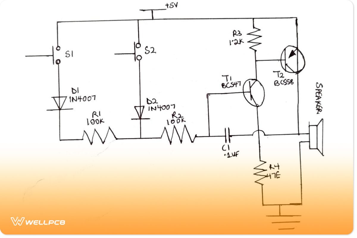
A Simple Security Alarm Circuit
When we press switch S2, the same situation occurs. The transistors T1 and T2, in the waking state, receive power from the diode D2, and this diode connects to the switch S2. As a result, the speaker produces the sound attached to it. But, in this case, we hear a high-pitched tone, indicating that an intruder is present near the locker. The only way to silence the alert sound coming from the speaker is to turn off the electricity.
Common Kinds of Alarm System Circuit
Generally, there are two alarm circuit types. They are the Burglar Alarm Circuit and the Fire Alarm Circuit. Though the correct terms are “unsupervised” and “supervised.” Unsupervised circuits make up several burglary zones. Also, supervised rotations are practical in analog fire circuits. That is why we are using the words Burglary and Fire. There are only two states in a burglary alarm circuit: open and end-of-line resistors. In an unarmed alarm system, an open burglary alarm circuit causes a FAULT condition.
Furthermore, S1 and S2 are the two circuit switches that work in the circuit. These switches can stay in two different locations, one in front of the locker and the other on the front door. When we press the switch S1, the diode D1 connected to it begins to conduct. Also, the transistors T1 and T2, with the resistor, begin to run. Transistors T1 and T2 receive positive feedback from the capacitor for oscillation. The low tone frequency generated when we press the circuit switch, S1, shows the presence of any intruder.
Burglar Alarm
Burglar alarms are commonplace in stores, banks, homes, or any place that requires extra security. They are operational 24 hours a day, seven days a week, and they safeguard the location from theft of valuables by ringing out whenever intruders enter.
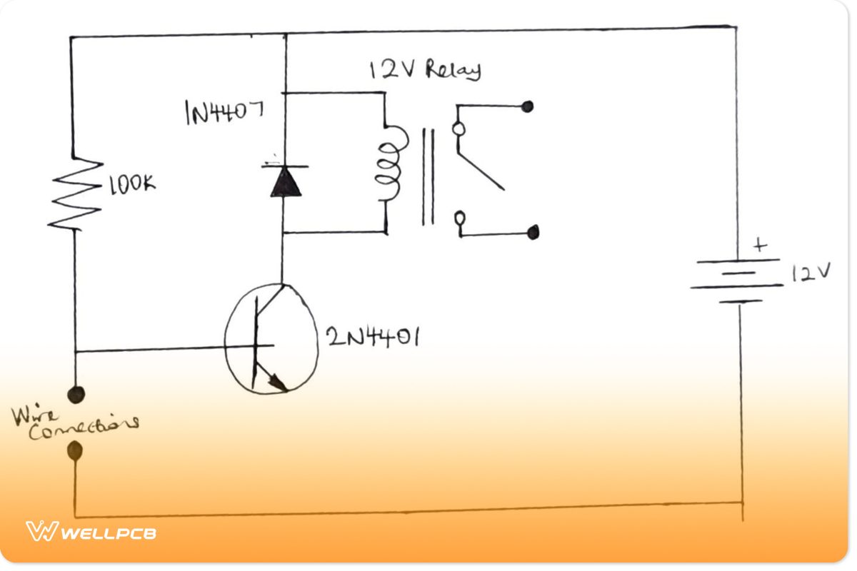
A Burglar Alarm Circuit
Fire Alarm
A fire alarm circuit has three states to do the requisite supervision: open-circuit system, EOL, and closed-circuit system. Next, we look at the functions of each circuit board of these alarms.
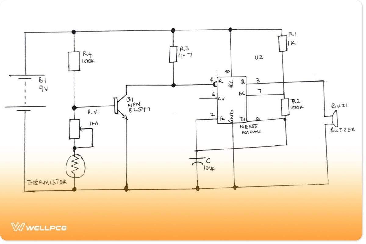
A Fire Alarm Circuit
Functions of Each Circuit Board
Using an Ordinary Conductor as the Sensor of an Intruder Alarm.
It is the easiest of the bunch. The sensor is a thin cable conductor that is spread across a limited region. Anyone who intrudes in the area comes in contact with the wire and triggers it. The transistor then receives the required information once the wire breaks. Thus causing the associated alarm to ring.
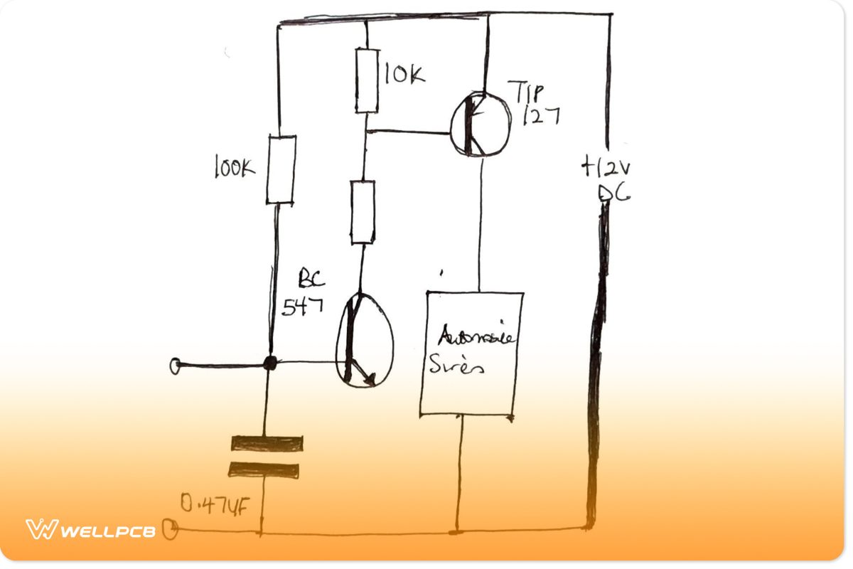
(Intruder Alarm Using an Ordinary Conductor as the Sensor)
Using a Piezo Sound Sensor in an Intruder Alarm.
The connected Piezo sensor uses a low-cost piezo element to detect sound. Overhead installation is possible for the complete system. The connected piezo sensor then detects an attacker trying to force their way in as soon as they disturb the door. It is achieved by activating the piezo sensor.
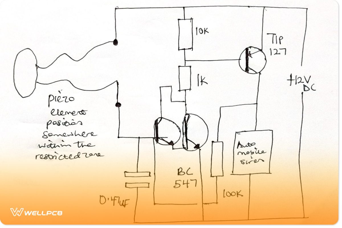
(Intruder Alarm Using a Piezo Electric Sound Sensor Circuit Image)
A Laser Beam Intruder Alarm.
The laser beam is helpful in an alarm sensor. This system uses a series of laser beams as the primary detectors, as well as strategically placed mirrors. A photoresistor trigger circuit receives the final reflection. Anytime an intruder trespasses the laser area, they trigger an intruder alarm. They do this by blocking any of the beams in the room. The security system either rings a Burglar Alarm, contacts emergency services, or lets out a silent alarm that notifies the occupants. Undoubtedly, it is a very creative and cost-effective way of informing you of the presence of intruders.

(A laser Security System in Action)
Intruder Alarm with Push Button ON / OFF Feature
This intruder alarm makes use of a single silicon-controlled rectifier (SCR), which toggles on or off the notice as needed.
Low Voltage Alarm Circuit.
It checks for problems with batteries and other volatile current sources. The circuit emits an alarm and illuminates an LED. But it also connects to a variety of different circuits for a variety of purposes.
How to Build a Base Alarm Circuit
Now that we know the working principle and common alarm circuit types. Next, we learn how to make a simple alarm circuit.
Required Components
- PCB.
- Few wires.
- BC547 Transistor.
- Battery connector.
- Ohms.
- Photoresistor.
- 9V Battery.
- LED.
https://youtu.be/OJXEP27Z-Bc (A DIY SECURITY ALARM CIRCUIT)
Functions of the Circuit Components.
- LED: These are flashing lights used in testing the functionality of a circuit.
- PCB: It uses conductive routes to Support mechanical and electrically connected electronic components.
- Photoresistor: A photoresistor determines when the light should be on or off.
- Battery Connector: A battery connector is a device that connects two or more electric circuits.
- Battery: Batteries enable burglar alarms to work even when the power is switched off.
- Ohms: They incorporate electrical resistance into the circuit as a circuit element.
- Transistor: The transistor boosts weak input signals. A transistor has two PN junction diodes coupled in series.
Conclusion
Usually, a sensor, camera, motion detector, buzzer alarm, and batteries make up an alarm system. It’s the sensor that picks up on sounds or motion. By using this circuit, you keep valuables and other essential properties safe from prying eyes or theft. Install this circuit in your homes or wherever required. The buzzer goes off whenever anyone steps over/or triggers the alarms. So, if you have any questions or comments, you can always contact us.


