Circuit Board Fabrication and IPC Class 3 Assembly Turnkey Services
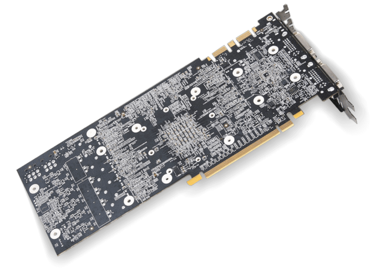
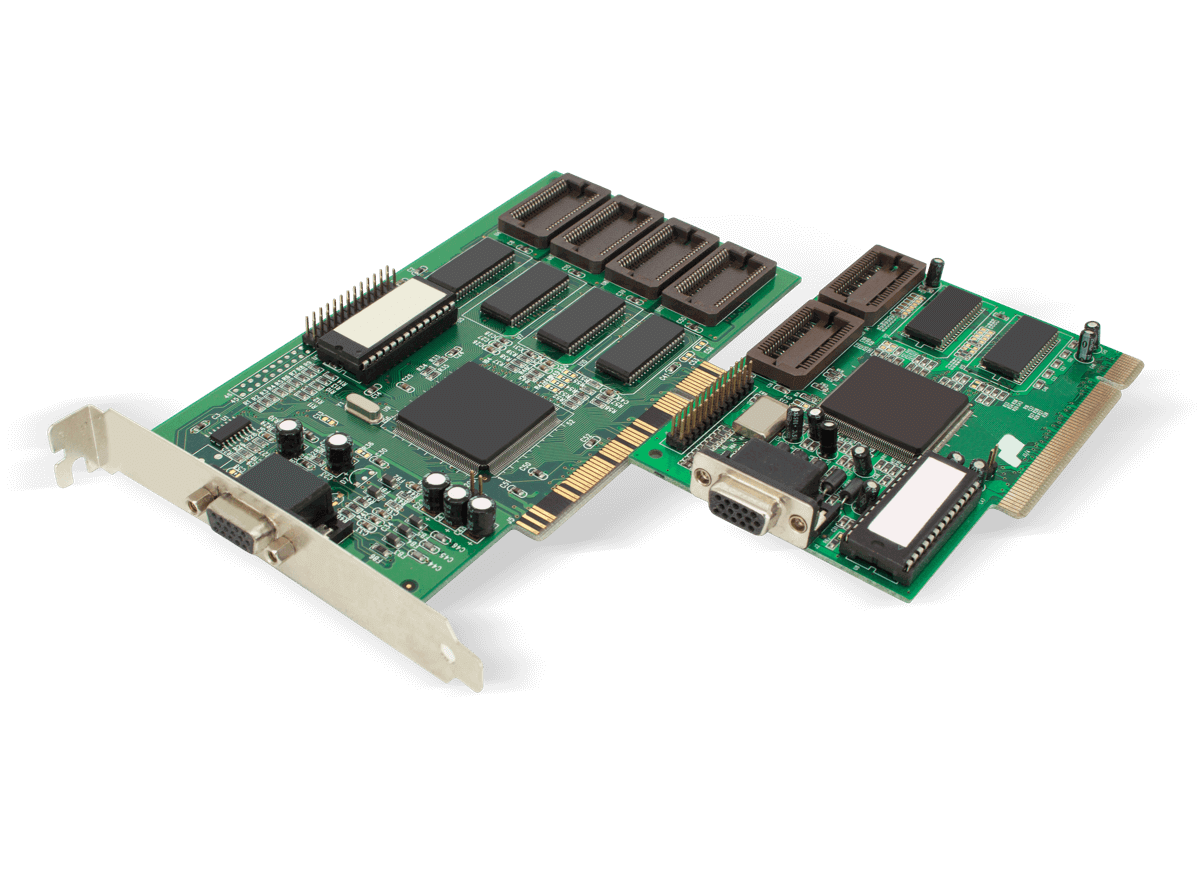
- PCB
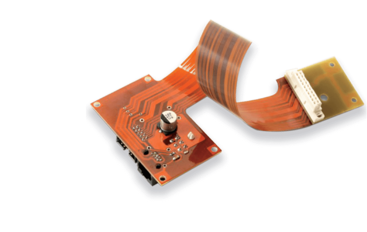
- Flex PCB
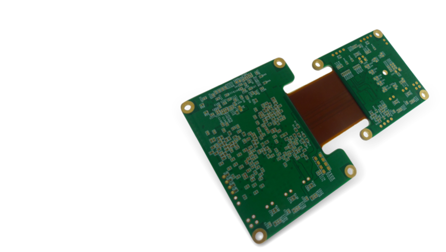
- Rigid-Flex PCB
Why Us?
Top-Notch Service
You can bank on us because we guarantee high-quality products and services that are World-class
All our products meet the UL or
IPC and ROHS&Reach Standards
Every customer order is paired with a dedicated account manager who assists with order placement and production initiation while ensuring smooth delivery and reliable after-sales support.
Best value at Affordable Prices
We brag of having one of the best competitive pricing globally, and we live up to it
We run our factories, so we've control of production post
There is never any hidden cost in our price quotations
We accept multiple payment methods like PayPal, Bank Transfer, Credit card, T/T, etc.
Both of our factories can support different orders and prices
Prompt Delivery
We support the standard shipping methods like DHL and FedEx—and we also carry out door-to-door delivery.
Our average shipping time is usually between 2 – 4 days
We have an affiliation with two reliable logistics company—that has been running discounted prices for our clients over the years
We carry out a proper inspection before we ship goods out—we even have an inspection certificate that meets the following; Moisture-proof, Anti-static, and Anti-vibration
There is a professional agent that ships to Pakistan and Iran
Super Easy Online Ordering
We deliver a prompt and instant online quotation at your request any time.
One stop service for PCB & PCBA
In-house PCB Fabrication
We only procure authentic parts
Stencil and IPC 6012 Class 3/A Assembly services
Traceability processing of pcb two-dimensional code laser marking
Superb Customer Care
At need to know about ordering custom PCB Circuit boards online. FOR the PCB board you need, you can contact us at WellPCB, we believe in "Customer first," so we always strive to give our customers the most reliable, convenient, and quality after-sale service.

Prompt and Detailed Prototype Assembling
When it comes down to PCB fabrication and IPC 6012 Class 3/A assembly turnkey services, our focus is to give you—our customer fast, reliable, affordable, and easily deliverable services, no matter where you are in the world.
Capabilities
- Lline Width / Space to 3mil / 3mil
- Blind&Buried vias
- Rigid, Flex, Rigid-flex
- Down to 0201 Size
- Double Side BGAs
- Controlled Impedance
- IPC 610E
- RoHS Compliant
- X-ray Inspection
- Pb-free, HASL, OSP, etc
- Mini.Hole Diameter to 0.15mm
- CNC / Metals
- Turnkey Assmebly
- Rogers 4350B\4003C
- Components Sourcing
WellPCB is Focusing on Printed Circuit Board Fabrication and PCB Assembly Turnkey Services
WellPCB is a subsidiary of Uniwell Circuits Co., Ltd, focusing on PCB fabrication and IPC 6012 Class 3/A PCB Assembly Turnkey Services.
We have two state-of-the-art factories and one PCB assembly factory founded in April 2007. Hence, the company aims to meet the dire demands of its customers—like you, across the globe—delivering easy ordering, high-quality products, and fast delivery at affordable prices.
Also, at WellPCB, we have novel and modern equipment with a production area measuring above 10,000m2, making it easy to produce approximately 2-32 layer PCBS of 30,000m2 feet while delivering more than 10,000 types every month.
Also, we deliver a quick 24-hour turnaround to deliver double-sided PCBs, a 48-hour turnaround for 4 -8 layer PCB, and a 120-hour turnaround for 10-layer PCBs and higher.
ABOUT US
Blog

Elevating Your Products with Custom Wire Harness Solutions
Every custom wire harness solution starts with a thorough analysis of the project’s requirements. This means determining the specific lengths, thicknesses, and materials to ensure a perfect fit, optimal performance, and lasting durability.
Unlike off-the-shelf solutions, customization makes it possible to develop reliable, cost-effective wiring systems for cutting-edge applications, from advanced machinery to vehicles, aircraft, and even spacecraft.
WellPCB is an industry leader in providing custom wire harness solutions, designing, fabricating, and assembling custom electrical harnesses for clients worldwide. In this article, we’ll explore our custom wire harness manufacturing process and the advantages of choosing a tailored solution
Testimonial


