Contents
Does a battery Desulfator really work?
A desulfator causes the built-up sulfate crystals in the lead-acid battery to fragmentize. After this process, the sulfur falls into the battery acid, where it dissolves. This occurs when a current pulse flows through the buildup. It can also extend the acid battery life.

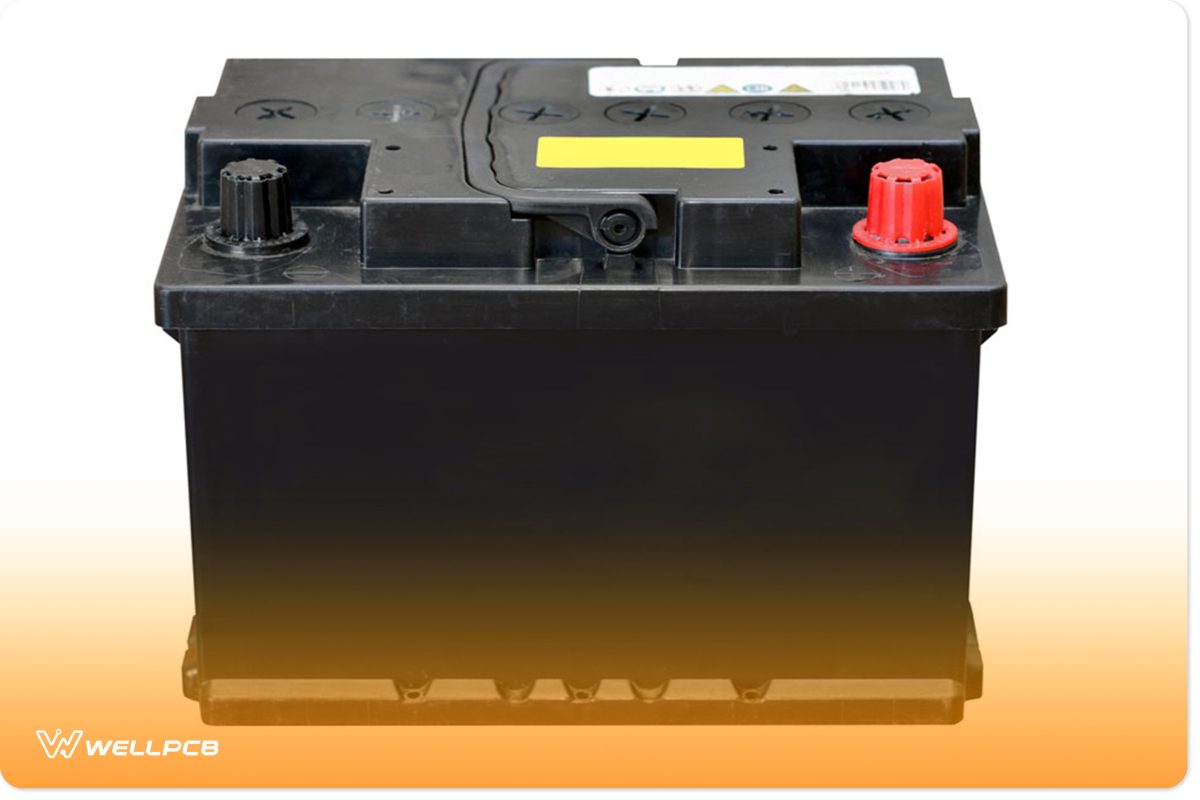
(Lead-acid battery)
How long does it take to desulfate a battery?
Desulfation times vary and usually depend on the battery’s size. A deep cycle battery will need an 8-amp setting to desulfate. While this occurs, the battery trickle charges, resulting in less lead sulfur. With that in mind, the entire process could end between 48 hours and a few weeks.
How do you desulfate a battery charger?

(Close-up view of sulfate crystals)
Some chargers offer battery desulfation features. For example, a recovery mode option detects sulfate crystals during the charging cycle. From there, it will automatically turn on and apply voltage pulses. However, this process only works for soft sulfation. To access this feature, press the mode button for three seconds and cycle through each setting.
Removing hard sulfation requires different technology. In this case, some battery chargers provide a repair mode. This involves desulfating a fully charged battery through a regulated electric charge. That process occurs by applying high voltages and low currents via the power source. When this happens, crystallized sulfation dissolves, transforming into active materials. However, it only provides minimal recovery because crystal sulfation stays there forever.
Exploring a simple battery desulfator
The two methods mentioned below provide simple solutions for battery sulfation.
Using PWM

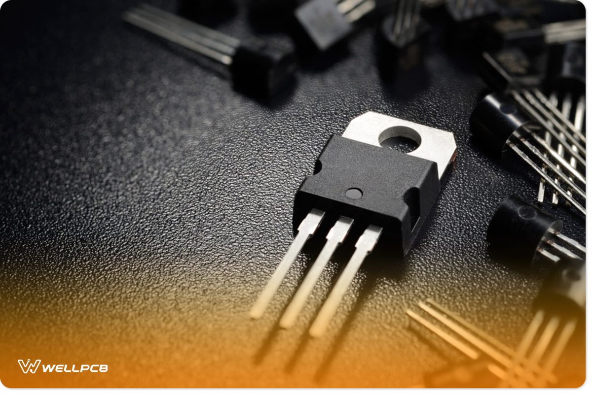
(The PWM control circuit contains two transistors)
You can desulfate a battery with energy stored through a PWM (Pulse-width modulation) control circuit, which also adjusts amp output. Using this method involves integrating a 555 IC timer. Two transistors intensify the IC’s output, allowing the battery to receive high-current pulses. And, to perform desulfation, the PWM’s control must contain a low mark ratio configuration.
The input’s current should be configured to a similar level as the battery AH level. Once the battery senses a positive response, the level progressively decreases.
Additionally, you can set the PWM control to equal mark/space ratios, which will provide batteries with a normal charge rate. However, we advise setting the PWM controls based on the battery according to the manufacturer’s guidelines. Failure to comply with the instructions could ultimately cause the battery to explode.
Desulfating with a Transformer and Bridge Rectifier Circuit

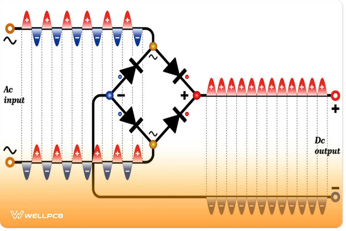
(An example diagram of a bridge rectifier circuit)
This circuit contains a 15V AC-DC power supply. Furthermore, we recommend integrating a transformer rated 25% higher than the battery voltage. With the transformer in place, the mains voltage steps down to 15V AC, ideal for the 12-volt battery. However, it converts to 15V DC via the bridge rectifier before reaching the sulfated battery terminals.
Initially, the resonant frequency is set to 50 Hz but increases to 100 Hz after the rectification process. That value changes to 120Hz if you integrate a 110V AC input. The bridge rectifier reverses the stepped-down AC’s lower half-cycles, merging it with the upper half cycles. As a result, it generates either a 100Hz or 120Hz pulsating direct current. Then, the pulsating DC breaks the sulfate off the battery’s plates. Additionally, you will discover that this 100Hz pulse prevents more sulfation. In turn, it also allows the battery’s plates to remain clean.

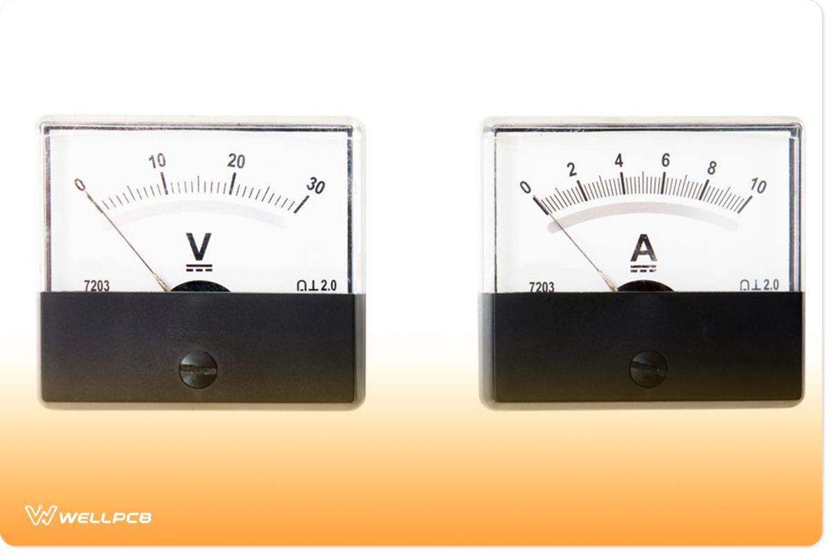
(An ammeter for this circuit)
An ammeter also connects in series with the power supply. This shows how much energy the battery takes in and displays the charging status in real-time. Plus, it monitors performance. Decent batteries will benefit the most because it shows the charging process. The needle’s indicator determines the battery’s charging rate, which slowly reaches zero. When that happens, the charging supply disengages.
Conclusion
Overall, desulfation provides the answer if an underlying problem exists with your battery. Not only does this technique cleanse the sulfate crystals from the battery plates, but it also assures longevity. This results in pulses reaching the terminals, causing sulfate to drop and dissolve. Usually, this can take anywhere from 48 hours to a few weeks to complete. Therefore, you should ensure you obtain a backup battery for your needs while performing this process.
Feel free to contact us if you have any questions regarding battery desulfation!


