Contents
What Is A Transistor?
Before we jump into what a BC547 transistor is, let’s cover what a transistor is. In a nutshell, it is an electrically controlled switch.
For this specific switch to work, it requires input, output, and a control line. In technical terms, we have the input as an emitter, the output as a collector, and the control line as the base.
Often, triggering the base current allows the emitter and collector to connect, thereby forming a switching element.
Likewise, you may also be familiar with the terms transistor and amplifier in one sentence. Why is that? The power between the emitter and collector can easily be higher than the base. For this reason, it is a common base amplifier.
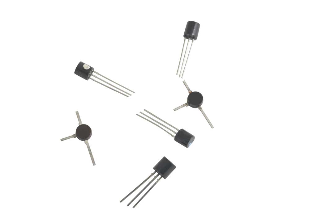
(Pictures of various transistors.
What is an NPN Transistor?
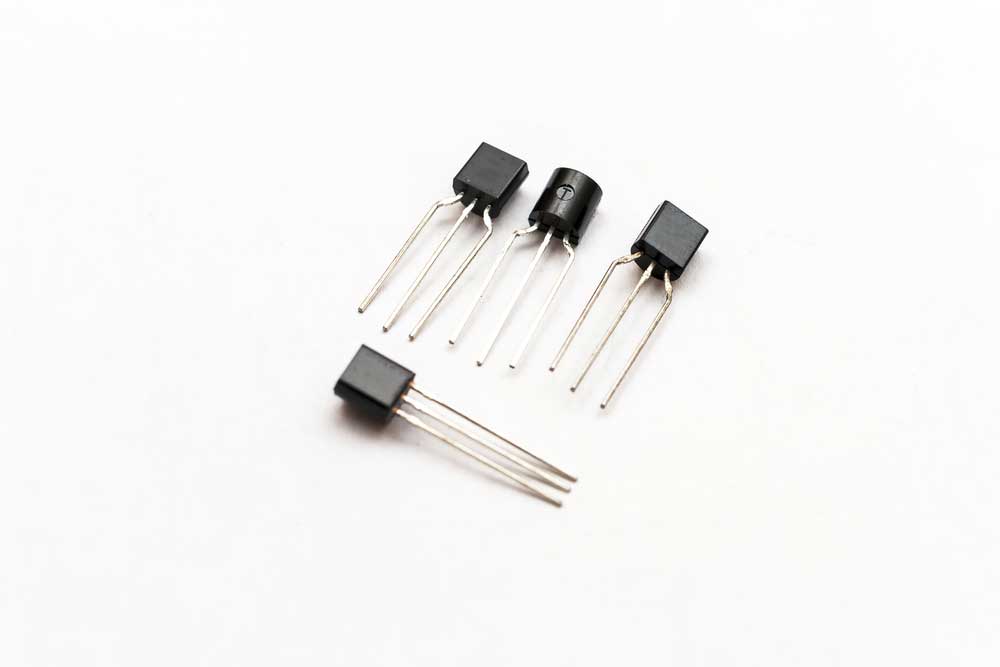
Examples of NPN transistors
An NPN Transistor (or negative-positive-negative transistor) is a general-purpose transistor used for signal amplification.
Furthermore, like most transistors, an NPN has three layers controlled by a collector current. These three sections are an emitter, base, and collector.
If you’re into electrics, you’ll already know that the flow of electrons makes this process work.
A diagram of the BC547.
What is a BC547 Transistor?
A BC547 is a type of NPN. When applying power to the control pin/ base terminal, the energy will flow from the collector to the emitter.
We’ll discuss this in more detail later, but usually, you’ll place this type of transistor after a circuit’s load.
BC547 Transistor Pin Configuration
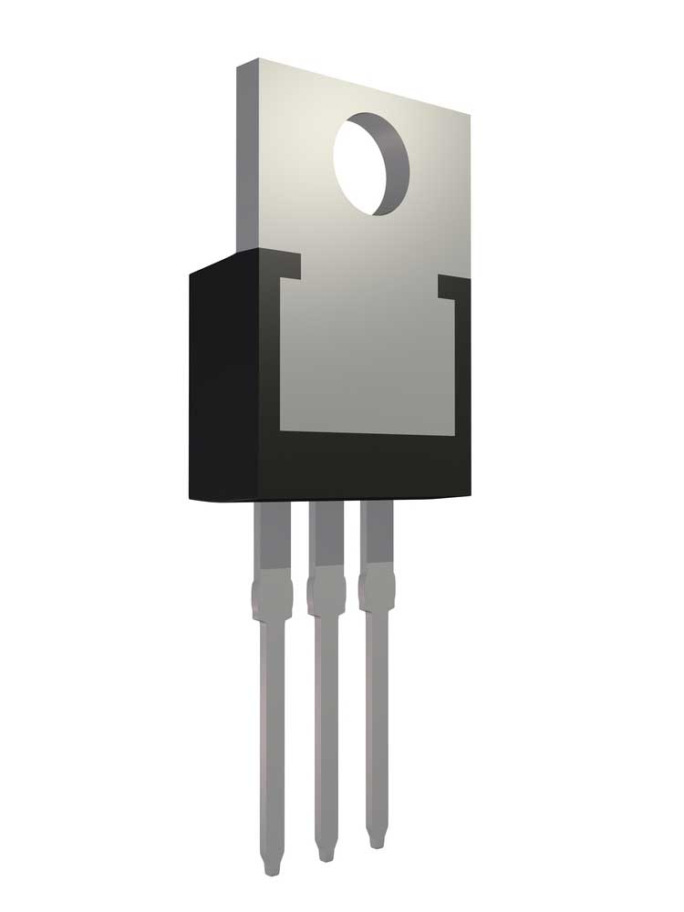
An example of a pin configuration.
Wondering what the BC547 transistor’s pinout configuration is? Here is everything you need to know:
Pin 1: Collector
Here, the current’s job is to flow through the collector pin.
Pin 2: Base
The base controls the biasing of the transistor.
Pin 3: Emitter
That current needs to go somewhere, and therefore, it drains out of the emitter.
Other specifications to know
Here are the necessary specs to look at:
- It is a Bi-Polar NPN Transistor.
- Secondly, its DC Current Gain (hFE) is at a maximum of 800.
- Then, it has a continuous Collector current (IC) of 100mA.
- Its Emitter Base Voltage (VBE) is 6V.
- Also, 5mA is the maximum Base Current (IB).
- Finally, it comes in a To-92 Package.
Characteristics of BC547 Transistor
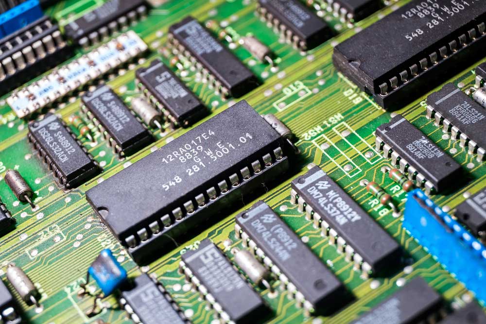
A circuit board with its electrical components, including a transistor.
Let’s dive into more details about the transistor.
Typically, the BC547 has an amplification capacity of 110 to 800. As for the maximum amount? The flow through the collector-base pin can only reach a max of 100mA.
Moreover, if you wish to bias a transistor, you can add a base terminal pin. However, the value should not exceed 5mA.
A fully-biased transistor
Once your silicon transistor’s bias is to its total capacity, a max of 100mA can flow from across the collector and emitter. Electric enthusiasts term this the Saturation Region and the flow is across the collector and emitter.
Typically, the emitter voltages allowed across the collector are 200 mV and 900 mV on the base. Then, the voltage measurement is in VBE.
As a result of this stage, and the fact that it is the cut-off region, the base voltage can reach 660 mV.
Application
As previously mentioned, a BC547 amplifies a current’s collector-base voltage.
It is also applicable for pulse-width modulation and quick switching.
Practical application of a BC547
Here are a few practical applications for your projects:
- In a DC device that requires a transistor for fast switching.
- To control the speed of a motor.
- In an actuator that needs speed control.
How to use Transistor BC547?
An example of transistors in our daily lives.

Ready to make your transistor? Let’s do it!
Materials you’ll need
1. 1x Breadboard
2. Connecting wires
3. 1x 5mm LED
4. 1x 9v battery
5. Assorted Resistors. 1K,33ohm should do the trick.
6. The most important part is a BC547 NPN transistor.
7. A switch
Circuit diagram
A diagram of the transistor.
Circuit description
This circuit allows the current to be turned on or off like in a light switch. In other words, turning it on allows the current to flow. On the contrary, turning the switch off limits or stops the flow of current to the device.
Simple steps
1: First, place the transistor on the breadboard.
2: Next, connect the emitter to the battery.
3: Then, connect the resistors and lead to the collector of the transistors.
4: Almost there! Now connect the resistors and switch to the base terminal of the BC547.
5: Last but not least, power it up with the 9V battery. You are done!
Conclusion
Used as a switch or an amplifier, the BC547 is common in everyday electrical work. This article discussed all you need to know about this transistor and how you can apply it to your work.
In conclusion, if you’re looking for leaders in the assembly and manufacturing field? PCB would be the place to be!
