Contents
What is a 2n3055 Transistor?
2n3055 is a general-purpose NPN transistor. It is currently controlled. Therefore, any small current at the base terminal controls a chunk of energy in the remaining terminals.
Also, conduction occurs when the movement of electrons and the charge carriers.

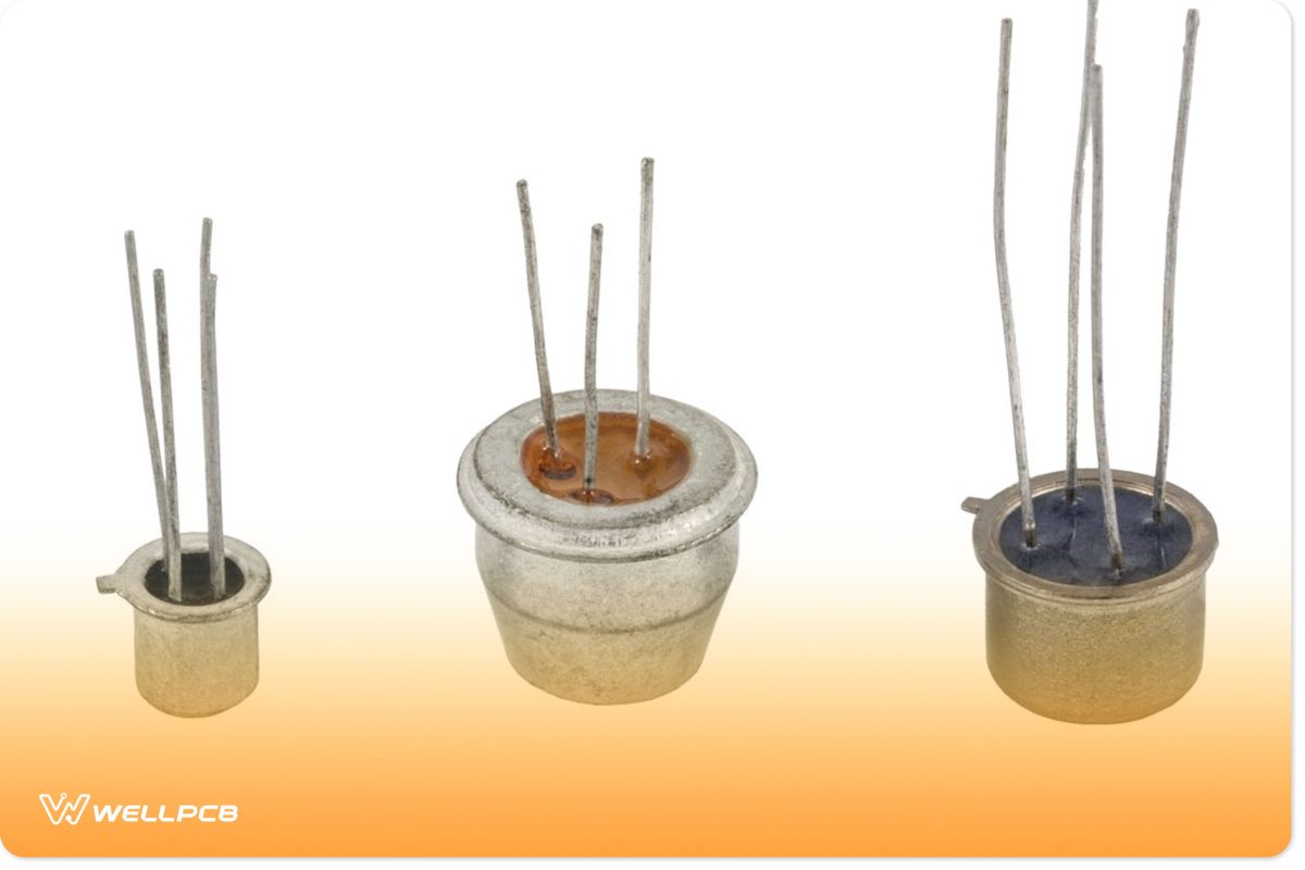
(low-power transistors in metal cases.)
2n3055 Transistor Pin Configuration


(three-pin transistors.)
2N3055 Transistor Features
- This transistor is a medium-power transistor with a very safe operating area.
- Second, the 2N3055 is an NPN complementary device in a TO-3 case style.
- Thirdly, its total power dissipation is 115W, with the maximum current flow through the base terminal being 7A DC.
- Additionally, 2N3055 has a DC gain(hFE) of up to 70A, improving the transistor linearity.
- The maximum rating of the voltage across the base and emitter is 7V DC. At the same time, the voltage rating across the collector and base is 100V DC.
- Further, the maximum current in the transistor’s collector pin runs at 15A DC. At the same time, the maximum voltage across the collector and emitter is 60V DC.
- The 2n3055 TO-3 case-style transistors also have a low collector-emitter saturation voltage.
- Lastly, the 2N3055 transistor has an ambient operating temperature range of -65⁰ C to +200⁰ C.

(a TO-3 style case transistor.)
How to use a 2n3055 Transistor.
Circuit Example
You can use the 2n3055 transistor in any bipolar transistor application. However, to understand how the transistor operates, we will use a simple application circuit.
In a typical emitter configuration, you will learn about the 2n3055 transistor as a switching device propelling a motor.

(2N3055 electrical circuit.)
Note: The trigger and power sources must share a common terminal for the circuit to work.
Circuit Explanation
The motor acts as the load from the circuit. The gate signal in the course has a button that, if triggered, turns the transistor ON.
Next, you should place a base resistor in the circuit after the button. This resistor limits the electric signals flowing through the base.
When there is no power supply in the circuit, the button remains open; thus, no current flows through the transistor’s base. As a result, the entire supply voltage of 20v(V1) is recorded.
But, when you push the button, the 5v(V2) voltage forms a closed loop with the base and emitter terminals.
This creates a complete path for the base current to flow through the transistor, rotating the motor.
On the other hand, when you release the button, the base current drops to zero, turning OFF the transistor.
The transistor lacks collector current and is in high resistance during this state, causing the motor to stop rotating.

(transistors in metal cases.)
Application
The application areas of the 2N3055 transistors;
- Power switching and in an amplifier circuit.
- Regular circuits and signal amplifiers.
- Pulse Width Modulation (PWM) applications.

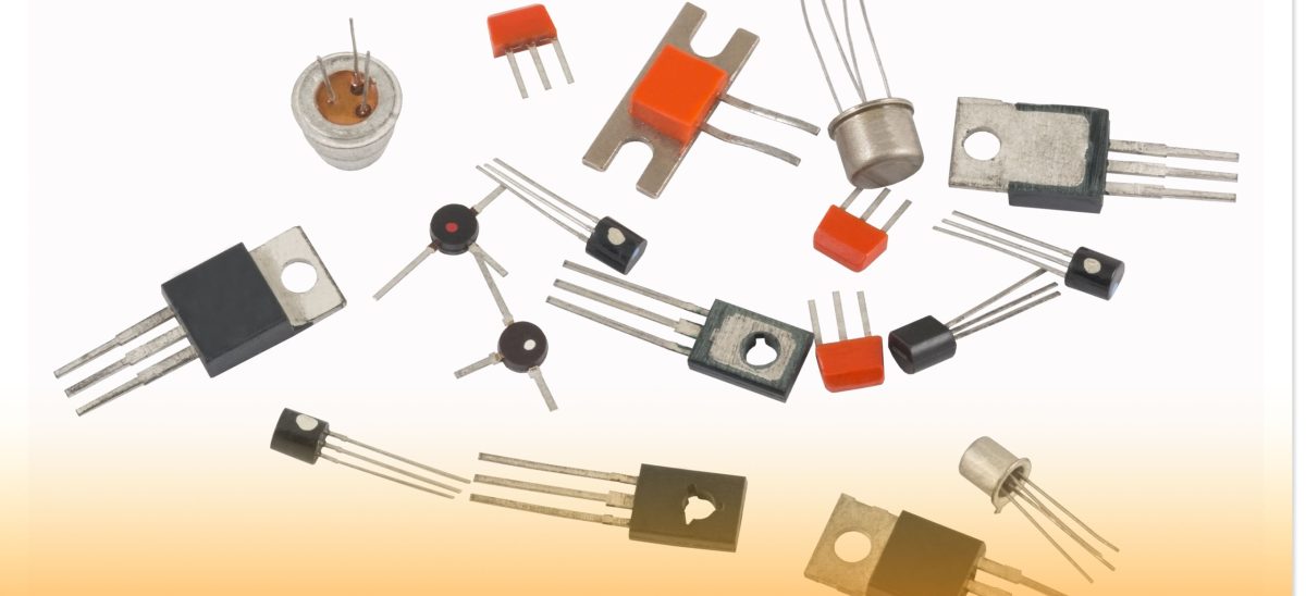
(a photo showing transistors.)
Summary
We hope this article answers your 2N3055 transistor-related questions. If you have any questions regarding this or any of our work, kindly don’t hesitate to contact us.
Our team is always ready to help!


