Contents
The Working Principle of Center-Tapped Transformers
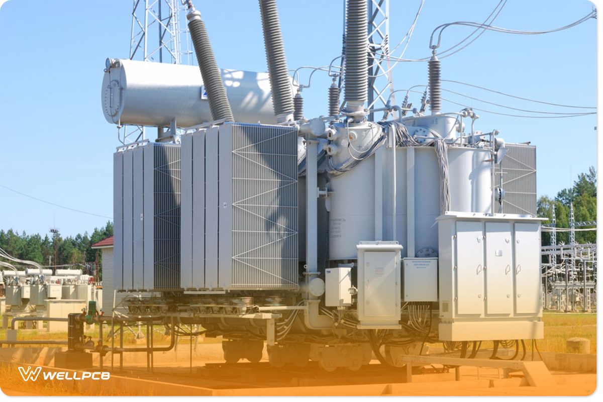
Fig 1: A Transformer in a Substation
The working of a center-tapped transformer is very similar to a standard transformer’s working.
Both transformers transfer primary voltage or energy from primary coils to secondary winding through inductive coupling.
The alternating current in the transformer primary induces a varying magnetic flux in the transformer core.
The induced flux cuts the secondary windings, inducing a varying voltage in the secondary winding. The core is from a material with excellent magnetic permeability, such as iron.
However, the secondary coil is tapped at its exact midpoint for center-tapped transformers. The center tapping enables three circuits from the output for different power needs.
You’ll have one circuit between the two ends of the secondary coil and the neutral. Furthermore, another circuit will be between the two ends of the secondary coil.
If you ground center tap, one-half of the output will be positive about the ground. The other half will be negative and 180° out of phase with the voltage in the secondary’s first part.
Therefore, you should ground the center tap to ensure you earth unsymmetrical currents that result from loads facing imbalance.
12-0-12 Centre-Tapped Transformer Specifications
Listed below are the specifications of a center-tapped step-down transformer.
- Mounting: Vertical mount type
- Input Voltage: 220 Volts AC
- Input Voltage Frequency: 50 Hertz
- Output Voltage: 0V, 12V, 24V
- Output Current: 1 Ampere
- Winding: Copper
Using a Center-Tapped Transformer

Fig 2: Close-Up of Electronic Circuit Board
The principle of operation is just like any other transformer. However, an additional wire is present in the secondary of the transformer.
Again, the center-tapped wire is a wire available in the middle of the secondary coil of the transformer. Thus, the sum of the voltages in the middle of the transformer’s secondary is always zero.
There is no connection between the primary coils and the secondary coils. However, when you introduce a voltage in the transformer primary, it induces a voltage in the secondary.
Assuming that the transformer is a 1:1 isolation transformer, a similar voltage is available in the secondary.
For our 220V step-down transformer, we will get a 24V AC output between either live wires T1 and T2. However, we’ll get a 12V AC output on either side of the center tap when the neutral is the reference.
For our transformer below, we shall take the voltage from the upper half of the secondary winding as Va.
In addition, we take voltage across the second secondary circuit as Vb, as shown in the schematic diagram below.
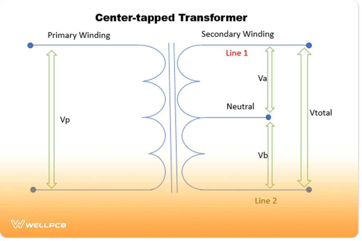
Fig 3: Schematic Diagram of a Center-Tapped Transformer
We can use the turns ratio formula to find the voltage across the secondary winding:
Va = (Na/Np) ✕ Vp
Vb = (Nb/Np) ✕ Vp
Where,
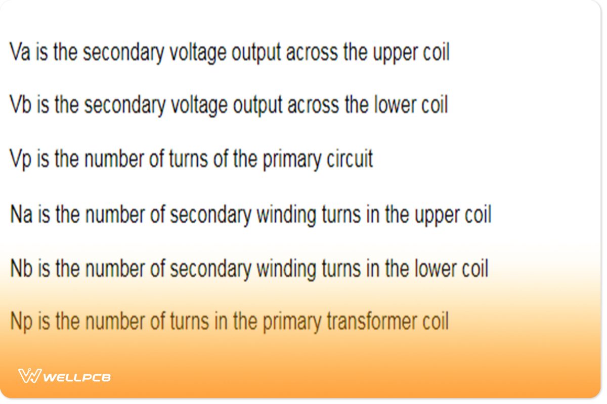
Difference between a Normal and a Center-Tapped Transformer
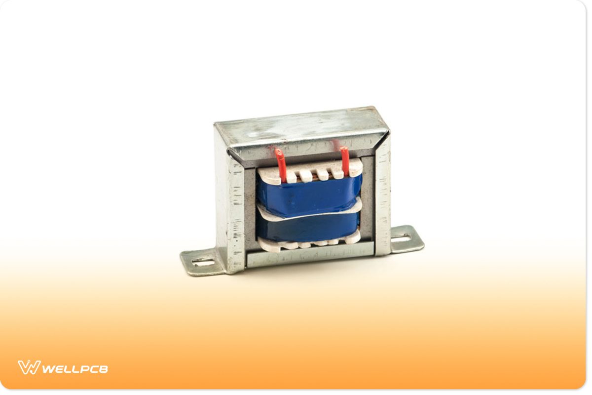
Fig 4: A Transformer
The primary difference is that a normal transformer outputs a single voltage. However, a center-tapped transformer provides you with three voltages depending on where you draw the voltage.
Applications of Center-Tapped Transformers
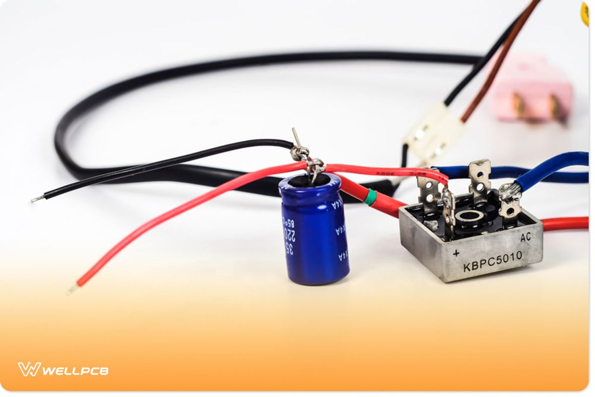
Fig 5: A Silicon Bridge Rectifier With a Capacitor
- DC Rectifier circuits
- Used as purely AC-AC step-down transformers
- Full-wave rectifier circuits
Conclusion
Center-tapped transformers are crucial in rectifier and AC circuits.
They enable you to split the secondary voltages in half and not damage your low-voltage devices. Furthermore, you can tap the secondary voltage for the more power-consuming devices.
If you need more information regarding center-tapped transformers for your project, we at OurPCB are willing to help.
Contact us today for more knowledge, materials, and resources on center-tapped transformers.


