
Contents
- 1 Understanding LED Polarity
- 2 Identifying LED Polarity: Essential Skills for PCB Assembly
- 3 The Pitfalls of Incorrect LED Polarity
- 4 Ensuring Proper LED Polarity in PCB Design and Assembly
- 5 Troubleshooting LED Polarity Issues on a PCB
- 6 Beyond the Basics: LED Polarity Considerations for Different Types
- 7 Ensure LED Polarity for your next PCB project.
Understanding LED Polarity
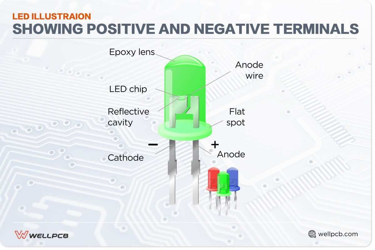
[Image: LED illustration showing positive and negative terminals]
LED Polarity ensures the correct alignment of LEDs, allowing an electrical current to flow and produce light.
An LED is essentially a semiconductor material within an electrical connection. When electrical current passes through the semiconductor, it emits photons as energy.
LEDs have two terminals attached to a small bulb. The positive pin (anode) is typically longer than the negative pin (cathode).
The anode is typically connected to the positive end of an electrical connection and the cathode to a negative one.
The color of the light emitted by an LED is influenced by the energy band gap, which is the spectrum between low-energy and high-energy electrons.
For example, red-light-emitting LEDs have high-energy electrons, while blue LEDs emit low-energy electrons.
The length of an LED’s lead (pin) is not a universally acceptable indicator of Polarity, as these are sometimes of equal length.
In PCB assembly that uses SMT technology, such as high-volume assembly, equal-length leads help ensure the correct placement during automated processes.
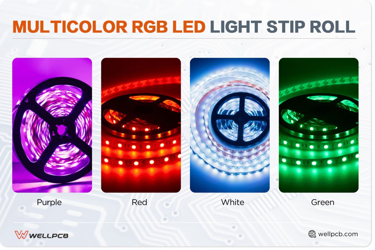
[Image: multicolor rgb led light strip roll ]
LED colors are not a direct polarity indicator, either. This is because colors are influenced by semiconductor material and the energy gap between conduction (high energy) and valence (low energy) bands.
Common semiconductor materials include indium gallium nitride, aluminum gallium indium phosphide, gallium phosphide, and aluminum gallium arsenide.
Here’s a table showing possible LED color emissions for different semiconductor elements.
| Semiconductor material | LED color |
| Aluminum gallium arsenide | Red and infrared |
| Indium gallium nitride | Bright UV, blue, and green |
| Aluminum gallium indium phosphide | Red, yellow, and orange |
| Gallium phosphide | Yellow and green |
Since LED color and lead length are not accurate polarity indicators, you must use other methods to identify Polarity. In the following section, we’ll identify and explain such methods.
Identifying LED Polarity: Essential Skills for PCB Assembly
Before PCB assembly, you need a foolproof method to correctly identify LED Polarity to minimize errors during the final inspection. Let’s explore three reliable ways to identify LED Polarity.
Refer to the Datasheet
The LED datasheet contains all the information a manufacturer needs during PCB assembly, including component name, electrical rating, and optical rating.
The document also indicates the negative and positive terminals of all LEDs involved in the assembly.
As such, you can check the datasheet to identify the Polarity of any given LED. Here’s an example of a datasheet:
Electric/optical characteristics at TA=25°C
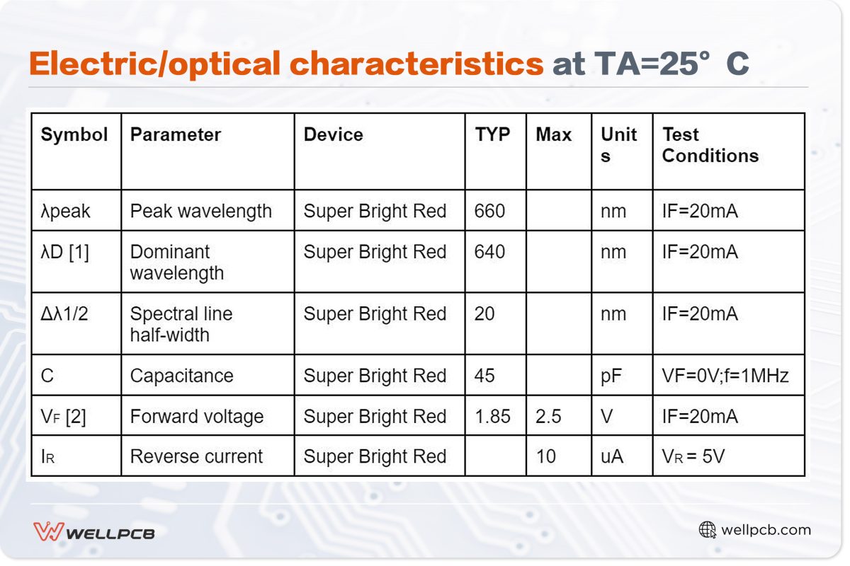
In the above table, which shows an example of a datasheet, the wavelength has a +/-1nm margin while the forward voltage has a +/-0.1V margin.
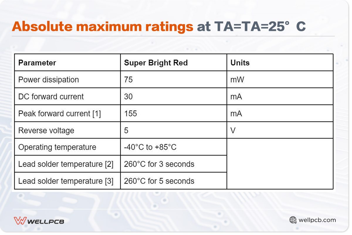
Absolute maximum ratings at TA=TA=25°C
Flat Edge Method
The flat edge method is a visual inspection technique for identifying an LED’s negative and positive terminals.
A typical LED has one flat side and one slightly curved side. The flat side is usually the negative terminal, while the curved side is the positive terminal.
This method is more accurate than looking only at lead length but is not universally reliable.
Multimeter Testing
Visual methods are prone to error, so using instruments like a multimeter to check LED Polarity is more reliable.
Follow these steps:
- Set the multimeter to diode mode.
- Place one probe of the multimeter on one of the LED’s pins (the black multimeter probe is negative).
- Place the other probe on the other pin.
- If the Polarity is correct, you should get an electrical reading on the multimeter display.
- If there is no reading, change the probe placement and check the screen again.
Hint: After using a multimeter, verify Polarity using a 9V battery. Connect the LED’s cathode to the battery’s negative terminal and the anode to the positive terminal. If the Polarity is correct, the LED will light up.
The Pitfalls of Incorrect LED Polarity

[Image: Electrician installing LED light bulbs ]
Correct Polarity is essential for critical parts of an electrical system to function. Without correct Polarity, systems that rely on indicators, displays, or warnings might not function properly.
Here are some potential issues caused by incorrect LED polarity:
No Illumination
The primary malfunction of incorrect LED Polarity is non-illumination. Unless the Polarity is correct, the LED will not light up.
This causes issues with visual indicators such as display screens, progress or status indicators, or warning signs.
Reduced Brightness
In some cases of incorrect Polarity, the LED may emit some light, but it will dim or flicker erratically. In sensitive LED applications, dim or inconsistent lights can affect functionality and cause damage.
Permanent Damage
Permanent damage from incorrect LED Polarity can occur in three different scenarios.
- The voltage applied in the wrong direction: LEDs are designed to light up with forward voltage application. Incorrect Polarity leads to excess current flow, causing overheating that can damage the LED.
- Temperature damage: Excess current from incorrect LED Polarity increases heat at the p-n junction, where recombination occurs. This temperature rise can permanently damage the semiconductor.
- Material degradation: Reverse current from incorrect Polarity can shift atoms within the LED, degrading its inner structure.
Ensuring Proper LED Polarity in PCB Design and Assembly
Correct LED polarity is essential for the reliability and functionality of electronic devices. Here are some best practices and key considerations to help minimize polarity errors.
Schematic Symbol Clarity
We mentioned needing a datasheet to ensure correct LED Polarity in the PCB assembly design phase. However, schematic symbol clarity is also vital in this stage. Each component, including LEDs, should have a clear and consistent symbol throughout the reference guide.
This clarity improves assembly accuracy and clarifies further documentation, especially for recurring assemblies. It also helps manufacturers avoid repairs resulting from reversed Polarity.
PCB Footprint Design
As incorrect LED polarity can lead to circuit failure—which affects PCB functionality—the design process must include the correct Polarity when creating the PCB footprint.
The manufacturer must create individual pad layouts for the LED’s cathode and anode pins, clearly marked with (+) or (-) to facilitate correct component placement.
The footprint design should indicate where other components can’t compromise LED function during assembly.
The footprint design isn’t complete without testing. Run a simulation to ensure the pad and LED pin alignment are correct.
Following the PCB Design
The PCB design guides the entire assembly process. You must follow the design specifications and datasheet guidelines to ensure the LEDs and the PCB work as intended. This approach helps avoid delivering faulty PCBs that cost time and money to rework.
Using Polarized Components
When PCB assembly is automated, we suggest preassembled polarized LEDs to minimize pre-assemble dime while ensuring accurate PCBs.
Troubleshooting LED Polarity Issues on a PCB
[Image: White Fairy Light ]
While LED polarity mistakes happen, you can reduce these errors during assembly with the following methods.
- Visual Inspection
Check LEDs visually to spot any inconsistencies. If you find damage or notice incorrect placement, replace the LEDs according to the datasheet and design manual.
- Power Supply Verification
Consult the datasheet to confirm the recommended power supply voltage and ensure the Polarity is correct to avoid reverse voltage.
- Multimeter Testing
Use a multimeter to check LED Polarity. We provided a step-by-step guide for this earlier in this article.
- Change the LEDs
Even if all LEDs have the correct Polarity, check the entire circuit to ensure each LED is correctly attached to the node or component. Replace any defective LEDs and check if they work.
- Final Test
Run a final check on the LEDs and observe any changes. Document all the fixes and tests for future reference.
Beyond the Basics: LED Polarity Considerations for Different Types
When assembling PCBs with LEDs in custom layouts, always consider different polarities. Here are some points to keep in mind:
Surface-Mount Devices
Surface-mount devices (SMDs) are usually placed on the PCB using automated processes like surface-mount technology (SMT). Larger components may require manual through-hole technology (THT).
In both assembly processes, refer to the datasheet for schematic symbols to ensure correct LED Polarity.
Precise alignment is crucial for automated processes to ensure PCBs come out functional and precise at scale.
LED Arrays/Modules
An LED array or module consists of multiple LED lights arranged in a strip or box panel, such as LED bulbs. The LEDs in these modules may have different polarities.
To simplify manufacturing and maintain correct Polarity, preassemble the module before including preassembly. This approach ensures a functional PCB with correctly aligned LED modules and fewer errors.
Ensure LED Polarity for your next PCB project.
LED Polarity goes beyond recognizing negative and positive LED terminals. Incorrect Polarity can have far-reaching effects, ranging from irregular lighting to complete PCB failure.
Correct LED polarity will ensure a PCB stays durable and functional. It also minimizes the cost and time required to address faulty batches resulting from polarity errors.
At WellPCB, our experienced assemblers, designers, and inspectors are leading the charge in PCB manufacture and assembly services.
Get in touch today to access accurate, correctly polarized PCBs in bulk for your business.
Check out our free learning resources for helpful tips and guidance on your next PCB project.


