Contents
header pins
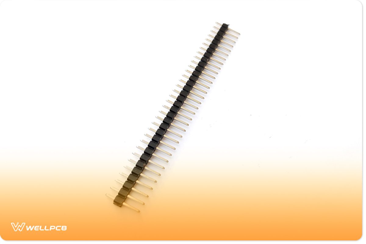
PCB header pins are commonly used to provide an electrical connection between two components or between a PCB board member.
However there are many types of PCB header pins, but mostly, it is the male connectors in a row separated from each other over a fixed distance.
Figure 2 shows a PCB header pin.

PCB socket pins
PCB socket pins are commonly used for mounting such components, which cannot be easily fixed on other connectors or boards.
Such features with single contact points are preferably selected on the PCB board using the PCB socket pins.
PCB socket pins exist in various ranges and dimensions to make it easier for users to choose one of their choices depending on their requirements.

Press-fit pins have evolved in recent years, allowing designers and engineers to use solderless press-fit connectors.
These PCBs pins are easy to use, making the production process less costly and more accessible than conventional methods.
In this case, it becomes significantly more accessible for the engineer to debug the circuit.

PCB alignment and guide pins support the components mounted on the PCB circuit board.
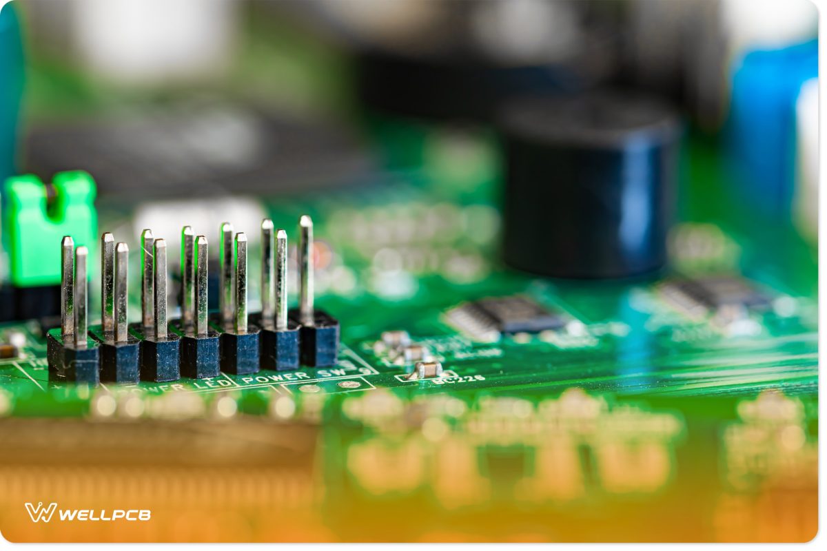
PCB solder pins are, however, one of the most commonly used PCB pins where the connectors are soldered onto the top of the circuit board.
Their typical applications are in prototyping and developing electrical circuit boards. Figure 3 shows a PCB solder pin.

PCB jumper pins
PCB jumper pins commonly provide a conduction path over an electronic circuit’s closed or open bypass part.
They are essential as the designer needs to provide a bypass connection to the electronic components used in a PCB board.
PCB terminal pins are designed to fulfill the growing requirements of the electronic industry.
The PCB terminal pins provide high current, separable connections onto the PCB board.
The various types and designs of these PCB pins allow the designer to work on different installation schemes for the designs.
The emerging improvements and advancements in PCB pins have made it significantly easier for engineers to work on prototypes and final PCB designs.
These developments have paved the way for executing many other complex designs, which seem impossible using conventional methods.
How Does a PCB Connector Work?
Printed circuit boards use PCB connector pins to transfer data signals or draw from a power source. This exchange typically occurs between two or more PCBs together.
As such, PCBs in applications single board computers and microcontrollers typically sport a PCB connector. PCB connectors are designed for temporary connections.
How to Test a PCB Connector
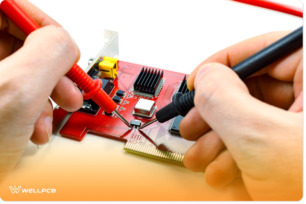
There are several ways you can test your PCB connector. You can use a glow wire test where you heat up a wire loop to a specific temperature and then apply it to the connector.
Alternatively, you can use in-circuit testing or X-ray testing. There are also dedicated PCB connector test kits that you can purchase.
How to Choose The Right Types of PCB Connector Pins?
When selecting a PCB connector pin, you need to consider factors such as type, pitch size and material. Type refers to whether the PCB connector is surface-mounted or uses thru-hole technology.
If you intend to use your connector to bridge circuit boards, then a thru-hole header PCB connector is best.
The pitch refers to the distance between pins. It also determines the length. Material is an important factor because it will determine the cost of production as well as the quality and conductivity of the PCBs connector pins.


