Contents
What is TDA1554Q?
The TDA1554Q is an integrated circuit, primarily a component for car radio amplifiers. It is a combined class B output amplifier with a 17-pin single in-line (SIL) plastic power package.
The amplifier chip can work as a 4x11W single-ended or 2x22W double-ending power amplifier. Additionally, the IC has four voltage amplifiers, with two being inverting and the other two being non-inverting.
TDA1554Q’s Pin Configuration
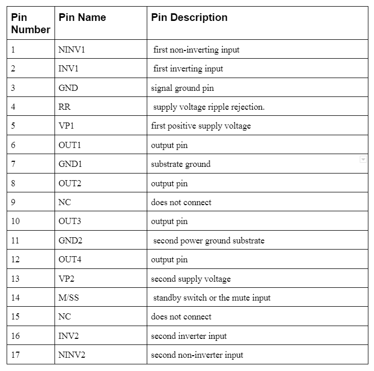
The 17 pins in the IC have different functions; therefore, refer to the circuit diagram for easy identification.
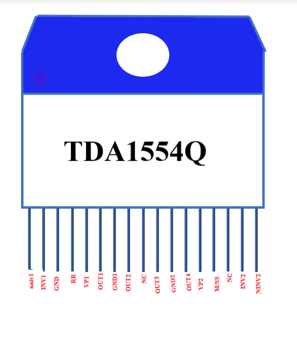
TDA1554Q pinout diagram
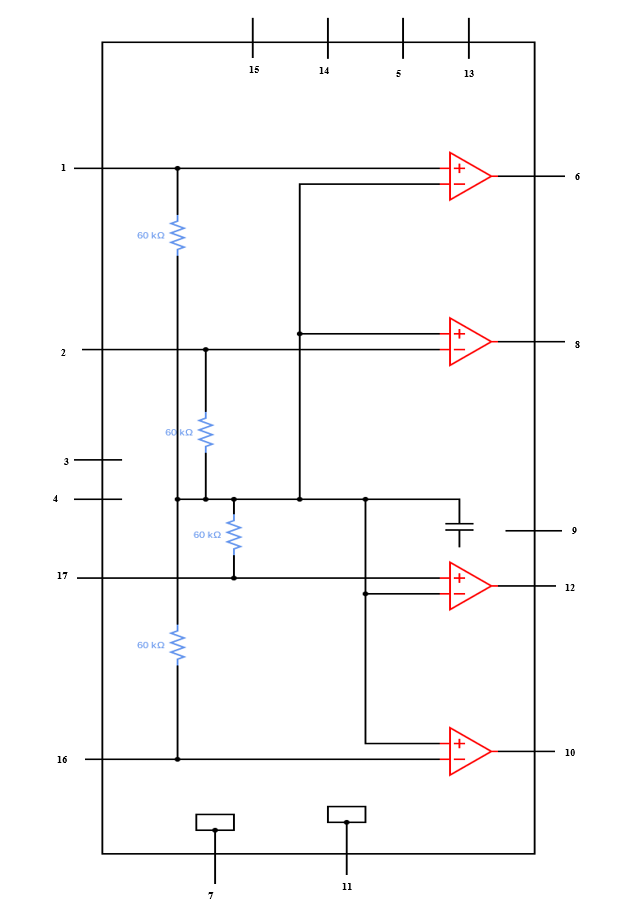
TDA1554Q circuit diagram
TDA1554Q Features
Firstly, it is easy to use because of its flexible leads, and it can work in a bridge-tied load (BTL) configuration or a quad single-ended configuration.
Additionally, it also has a mute/standby feature, and each of its identical amplifiers has a set gain of 20dB and 26dB in a BTL circuit configuration.
Other basic features are;
- Firstly, it has high output power and load dump protection.
- Secondly, A Low offset voltage at outputs is essential for BTL settings.
- Also, the circuit design is safe from reverse polarity and electrostatic discharge.
- Fourthly, it has thermal protection and low thermal resistance to handle heat production in the circuit.
- Lastly, an input impedance of 50kΩ to 50kΩ.
How to use the TDA1554Q Amplifier
The integrated circuit can work as a 2*22-watt amplifier, as shown in the circuit diagram below. The circuit configuration is also known as a BTL audio stereo.
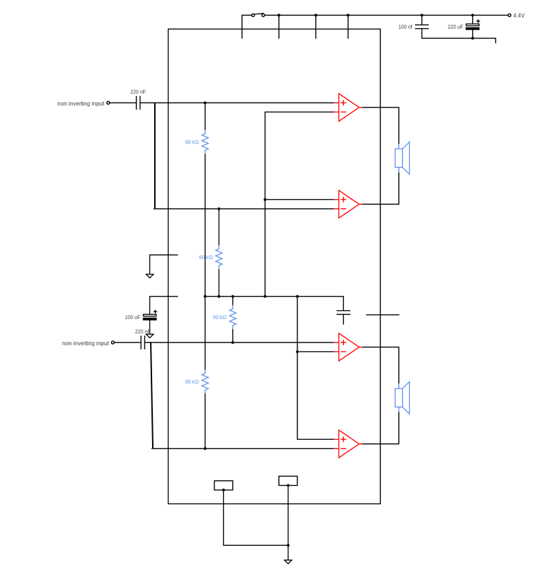
TDA1554Q is a bridge amplifier circuit
Remember that the circuit produces heat; therefore, it is necessary to have a good heatsink for optimal functioning.
The ideal operational voltage of the circuit is 12V and a current of 5 amps, hence making it suitable for a mini amplifier.
Additionally, each speaker connects two half-bridge MOSFETS that can work with an 11-15V power supply voltage.
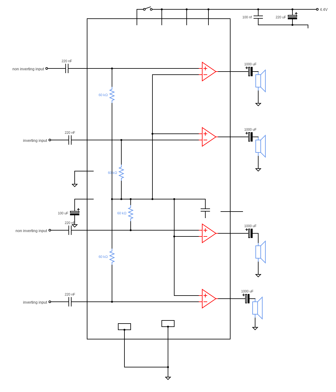
TDA1554Q is a Quad single-ended application connection diagram
The audio amplifier chip can also work in a 4*11-watt audio amplifier circuit. Each speaker connects to the course via a capacitor of 220nF capacitance in the quad single-ended configuration.
The capacitors work as filters that allow specific frequencies and restrict others, reducing noise voltage in the IC.
Conclusion
Hopefully, this functional description of the amplifier circuit furthers your understanding of the chip. It can work with 4-ohm or 8-ohm speakers, depending on the setup.
If you have a question, don’t hesitate to reach out to us.


