Contents
Understanding Surface Mount Technology (SMT)
SMT is a PCB assembly process for compact circuit designs. It directly mounts components onto the
PCB surfaces through advanced automation—a quick process that results in a compact, reliable design.
The SMT assembly process is broken down into the following steps.
Step 1: Solder paste application
A printer deposits solder paste onto a metal stencil with cutouts that align with the best component placements.
This ensures the right amount of paste is placed correctly on the board.
The applicator dispenses the paste through the openings on the stencil, which ensures the correct placement and amount of paste is applied to the PCB pads where components connect.
Step 2: Component pick and place
In this step, a gripper nozzle takes out all the desired components from their package, including:
- Capacitors
- Resistors
- ICs
- BGAs
Next, a pick-and-place machine adds the components to the correct areas of the PCB where the paste has already been applied.
The pick-and-place machine then orients each component before placing it in the correct position on the board.
Step 3: Reflow soldering
A reflow solder oven heats the solder paste and components placed on the PCB.
This process melts the solder. As a result, all the components connect securely into place, ensuring a solid attachment to the board once the solder and components cool.
Step 4: Optical inspection
Lastly, an inspection takes place. This involves using X-rays, flying probe testers, automated optical inspection (AOI), and more.
These methods aim to find issues on the PCB, such as:
- Missing or misaligned components
- Open circuits
- Solder shorts
- Excess solder
- Other issues that impact product quality
Benefits of SMT assembly
SMT has many advantages, especially for those looking to build smaller, more specific products with their PCB. Key advantages include faster assembly and improved electrical performance.
- It enables miniaturization and high-density designs.
SMT involves integrating smaller components. This leads to the production of more compact, portable devices.
Due to component size, SMT assembly often enables high-density designs because those components connect closely on a smaller board.
As a result, complex, high-density circuits fit and function in a smaller design.
- It allows for a faster assembly process for large volumes
SMT assembly is quicker and more precise thanks to pick-and-place machine automation. This process saves time, especially for large assembly volumes, as pick-and-place machines don’t slow down when mounting multiple components simultaneously.
- It improves electrical performance.
An SMT-based device will exhibit a boost in electrical performance. This occurs because circuits assembled using SMT techniques experience decreased lead inductance/capacitance and signal trace length on the circuit board.
Electromagnetic interference isn’t as problematic because components are mounted closer together due to better shielding and grounding.
Disadvantages of SMT assembly
Of course, the drawbacks of SMT assembly can make the decision more challenging. It can be harder to do correctly without specialist expertise and equipment, leading to higher costs.
- It has higher upfront costs compared to THT.
SMT assembly is generally more expensive than THT. One reason for this is the equipment. Pick-and-place machines, reflow ovens, and automated inspection are generally more expensive than equipment used in THT.
However, the compromise is that SMT assembly methods use advanced technology with better accuracy for smaller components. SMT also requires stencils to apply the solder paste, further increasing costs.
The cost of setting up the SMT assembly is also higher. The process includes equipment programming, automated system configuration, and production line setup.
- It may require specialized equipment and expertise for the assembly
Special SMT machines are complex. Because of this, SMT requires intricate fabrication along with rigorous control.
Equipment operations and SMT assembly management rely on expertise, which can only be achieved through training. Otherwise, operators might not know how to use the machinery and precisely mount the components, resulting in more errors or safety risks.
- Less suitable for large, high-power components
SMT can pose challenges when working with power-intensive components, like large capacitors and power transistors.
These need strong mechanical connections and a lot of current/thermal dissipation, which can damage an SMT board.
Mechanical stress will also impact large components, possibly affecting solder joints. That happens due to weaker connections in the board that don’t fully support those component pins.
Exploring Through-Hole Technology (THT)

THT is an older assembly process. This technique incorporates circuit components through pre-drilled holes, providing a stronger connection and protecting the board against harsh elements.
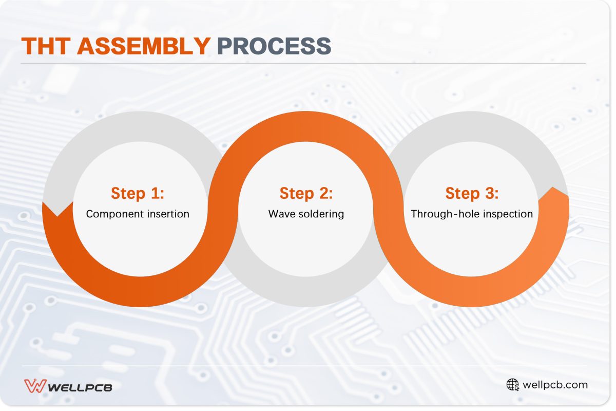
Here is the step-by-step process of THT assembly.
Step 1: Component insertion
With the THT method, components mount manually or automatically.
Manual insertion involves workers placing components into the circuit board holes by hand. They must factor in component height, position, and orientation during this stage.
On the other hand, automated insertion uses machinery such as the Universal Instruments Radial 88HT. These automatically shorten leads, determine polarity, and insert all components into place.
Step 2: Wave soldering
In this step, the PCB moves through wave-like molten solder, connecting multiple components simultaneously for maximum efficiency. The solder then passes through the holes in the board to secure all the component leads in place.
Step 3: Through-hole inspection
Like SMT assembly, the inspection phase involves using techniques like AOI, x-ray, and manual/visual inspection to identify defects. Electrical testing is often used to confirm if the PCB works as intended.
Benefits of THT Assembly
THT assembly has advantages that make it an attractive option, including lower upfront costs and stronger connections between components.
- Lower upfront costs compared to SMT.
THT assembly is a more affordable alternative to SMT. It uses less costly, simpler wave soldering (or selective soldering) machines for low-volume and medium-volume production.
In addition, THT components aren’t as expensive as their SMT equivalents, which helps keep costs down.
Manual component placement (soldering stations) also affects THT assembly’s cost-effectiveness. Since there’s no need for an automated system in this case, it requires a lower overall investment toward setup and operations.
- Stronger mechanical connections for robust components
Component leads are placed into drilled holes, and soldering occurs on the other side of the board, creating a strong mechanical bond.
As a result, mechanical stresses like shock, vibrations, and temperature fluctuations won’t significantly impact THT-assembled components.
- Easier rework and repair possibilities
Workers can use desoldering tools and solder irons to remove THT components from the PCB. This makes it easy to perform repairs, rework, and replace components.
Reworking is easier, thanks to the large component sizes seen in THT assembly. This means damage is less likely to occur—especially because components have stronger overall mechanical connections to the board.
Disadvantages of THT Assembly
THT also comes with disadvantages. These give a good grasp of what to expect when choosing this option, such as an overall slower assembly process, though this is perfect for building larger PCBs.
- Larger footprint compared to SMT, limiting miniaturization
Components involved in THT assembly methods tend to be larger, making it difficult to create compact, portable electronics.
Instead, THT is ideal for creating larger PCBs.
- Slower assembly process for high-volume production
Producing high-volume PCBs assembled via THT takes longer and requires more work. That comes down to hole drilling, component lead placement, and soldering for each circuit board, regardless of whether your process is manual or automatic.
- It may have lower electrical performance in high-frequency applications
THT components have longer leads, potentially leading to parasitic capacitance. These also carry a higher risk of electrical signal problems or loss.
Head-to-Head: A Comparison of SMT and THT
Let’s review the details to summarize the differences between SMT and THT assembly techniques.
| Category | SMT (surface mount technology) | THT (through-hole technology) |
| Soldering techniques | Reflow soldering A reflow solder oven sets the solder where the components connect. The process is often automated. |
Wave soldering The solder flows into the PCB holes, soldering each component, often with manual input, though automation is possible. |
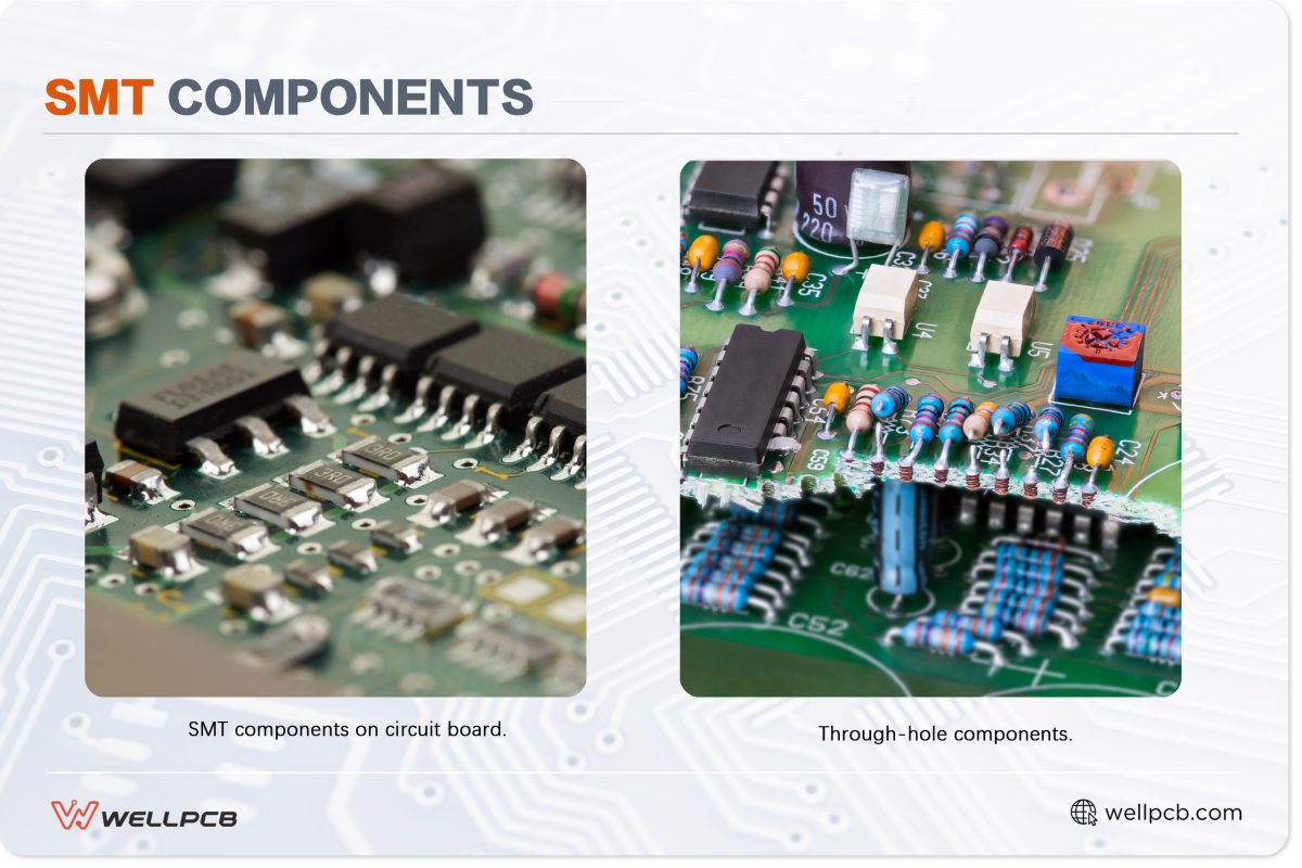
| Component types | Surface mount components: Integrated circuits Surface-mount LEDsSOT-23 and SOT-223 transistorsResistorsCeramic, electrolytic, and tantalum capacitorsSurface-mount diodes (SOT-23 and SOD-323) |
Leaded components: Integrated circuits (dual in-line packages)Through-hole LEDsTO-92 and TO-220 transistorsAxial-lead resistorsRadial-lead capacitors Axial lead diodes (rectifier and Zener) |
| Advantages | More affordable Smaller, lightweight PCBsQuicker to assemble High-frequency circuitsHigh component density | Easy to rework, repair, and replace componentsHandles mechanical stress Better mechanical bond Used with power-intensive components |
| Disadvantages | Affected by mechanical stress Difficult to rework | Requires a bigger PCBMore expensive It takes longer to assemble Low component density |
| Ideal applications | Large volume manufacturing Small devices like smartphones Very dense PCBsHigh-frequency circuit | Low volume manufacturingPrototypesHarsh environmentsAerospace (planes, space shuttles, and satellites)Large PCBs |
When to choose SMT?

Selecting an SMT assembly method can prove beneficial in several scenarios:
- High-density and miniaturized electronics: Manufacturers may choose SMT for small electronics with high component density. Examples include wearable devices, tablets, laptops, and smartphones.
- Cost-sensitive applications with large production volumes: When dealing with large production volumes, SMT can slash costs due to the automation process, making it a viable cost-saving solution in the long run.
- Improved electrical performance prioritization: SMT is ideal if the application (high frequency) requires minimal parasitic capacitance and inductance, ensuring stable electrical performance.
When to Choose THT?
THT is a great choice for PCB assembly under the right circumstances:
- High-power components requiring robust connections: Power-intensive components, like transformers or power transistors, produce significant heat and must handle a high current load. THT — which offers mechanical stability and thermal dissipation — is ideal for circuits with those parts.
- Applications requiring strong mechanical stability: Environments with a high risk of shock, vibrations, and heat can cause poor PCB performance. In this case, THT assembly techniques can provide mechanical stability and keep everything in excellent condition.
- Prototyping or low-volume production: THT is a fairly simple manual assembly process. This means it works well for early production, research and product development stages that require quick refinements to your PCB.
- Easier rework or repair is needed: Industrial use cases like automotive systems may benefit from using THT because they often require rework or repair on larger components.
We Deliver on Both Fronts: SMT and THT Assembly Expertise
WellPCB handles SMT and THT assembly processes for the right circuit projects, excelling in efficiency, precision, and proficiency.
More importantly, we deliver high-quality standards and rigorous quality control procedures, ensuring the PCBs we assemble meet the highest industry standards. Are you ready to work with WellPCB? Get a quote for your next PCB assembly project today!


