
Contents
List of Components Required for the Project
The following is the entire list of components you would need to do the project.
- Resistors of different values (70K, 10K, 50K, and 5K).
2. Capacitors of different values (470uF and 0.01uF).
3. IC of Operational Amplifier, i.e., LM741.
4. An IC of the timer, i.e., IC555.
5. A transistor.
6. A bulb or Lamp of 12 Volts.
7. Wires for circuit completion.
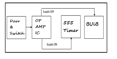
How To Design Automated Light For Bed Room—Simple Block Diagram
The following is the simple block diagram of the circuit.

Working on the Circuit and Schematics
The IC of the operational amplifier has eight pins and pins 2 and 3 are for the inputs. In contrast, pin 3 is for the non-inverting information, and pin 2 is the inverting input terminal.
Pin 3 is given a fixed voltage with the help of a potential divider, whereas, at pin 2, the input voltage is provided through the switch.
The button is being used in the closed position, i.e., the SPST switch is being used. The output of the operational amplifier is fed to the IC of the timer, i.e., 555, which, when triggered, generates a very low voltage at the input terminal 2 and generates a high pulse at terminal 3 of the OP-AMP IC.
Now, the operational amplifier’s output is connected to the Lamp 12 volts.
The basic circuitry or schematic diagram of the project is as follows.

As evident from the schematic diagram, the switch must be placed over the room’s wall.
The way is such that when the room door is opened, the light gets ON automatically when the trigger of the switch is pushed.
When the motivation of the button is made, the connection through the switch is completed, and it gets ON.
The IC of the operational amplifier works as a comparator when the switch is opened, the inverting terminal of the OP-AMP IC is connected to the Lamp, and voltages of almost 4 Volts are generated, which are fed into the non-inverting terminal of the OP-AMP IC.
Now at the non-inverting terminal of the OP-AMP IC, the voltage is lesser than that of the inverting terminal of the IC. Therefore, a novel pulse is generated at the output of the IC, which is fed into the 555 timer IC with the help of a potential divider arrangement.
By this time, the IC of 555 timers is getting triggered with the help of low voltage signals at the input side, and in return, it generates a very high pulse at the output terminal.
Now, the timer is working in the mode known as the mono-stable mode. Here, when the Lamp receives a signal of 12 volts, it glows automatically.

When you come out of the room, you will close the door, and the entire process will reverse. The switch would get back into its original position and would get close.
This is because the non-inverting terminal of the operational amplifier IC is getting higher voltages than the inverting terminal. This fails the trigger to get ON, and the lights are made OFF and don’t get 12 volts.
The PCB Design of the Circuit
The project’s basic layout of the Printed Circuit Board is given below. Numerous methods can be used to make the Project’s Printed Circuit Board. However, WellPCB is a good choice for printed circuit board manufacturing.


