Contents
Simple FM Receiver Circuit

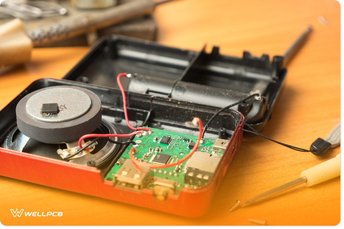
Fig 1: Repairing a radio FM receiver
Circuit Diagram

Components Needed
Circuit Explanation
The radio circuit diagram above is that of a straightforward FM receiver.
Here, the transistor T2, resistor R1, variable capacitor C, coil L, and transistor T1’s capacitance form a Colpitts oscillator. Variable capacitor C sets the circuit’s resonance frequency to respond to what we’d want to hear.
In other words, it sets a radio frequency between 88-108 MHz for the specific station you prefer. The resistor R1 extracts the signal, which moves through the coupling capacitor C1.
Afterward, you’ll hear a sound over your high-resistance headphones or small speaker.
FM Receiver Circuit Using LM386 and BF494

Circuit Diagram
Components Needed
Circuit Explanation
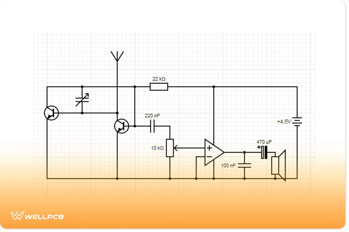
The circuit powers from two 3.6-volt lithium cells or a small 4.5-volt battery for better efficiency.
Also, the two RF transistors (BF494) in the FM receiver section identify the frequency-modulated signals.
Next, the trimmer capacitor and coil L1 couple to form the tuned tank circuit to adjust to the best FM station. Next, the signals pass and get coupled through capacitor C2.
The LM386 works between 4.5 and 12 V DC and is the circuit’s audio amplifier. You can control the volume that gets to the amplifier input using the 10k preset VR.
After amplification, you will hear the sound through a small Mylar speaker or low-impedance headphones.
Conclusion
FM receivers or radios are easy to design and manufacture because all you need to do is convert the frequency of radio waves into sound.
We’ve gone through the basics to guide you with your simple FM receiver project. Feel free to contact us for clarification or assistance.


