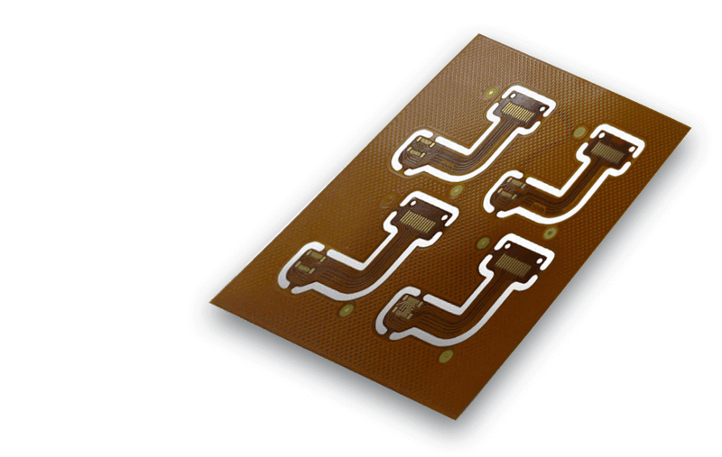
Flexible PCB Service
- High Temperature & High-Density Applications; Saving On Space and Weight
- Quality assured with more Reliability & Durability
- Flexible PCB Lead time: Usually 5-6 days(depends on your special design)
- WellPCB has a complete in house Fabrication and Assembly printed circuit board manufacturing plant capable to take your application from concept to production.
- We provide Flexible PCB Manufacturing & Assembly as well as multilayer flex circuits and also provide SMT component assembly on these products.
- Whether your circuit needs are for flat flexible cable, FPCB with Impedance, HDI Flexible PCB Board, FPCB with Immersion Gold, ENIG+OPS, or other, we have the capability to meet your needs.
Flexible PCB
capabilities
-
Specification:PCB Capability
-
Layer Counts:1-4Layers (Ultimate: 5-8Layers)
-
Tolerance of Finger Width:30.1mm (Ultimate:30.05mm)
-
Min Distance Between Pads:4mils (Ultimate:3mil)
-
The Thickness of Finished Product(Flex Part,No Tiffener):0.05-0.5mm (Ultimate:0.5-0.8mm)
-
Type of Surface Treatment:OSP HASL, Lead-Free HASL, Immersion Gold, Hard Gold, Immersion Silver, OSP
-
Impedance Tolerance: Single-Ended:±5Ω(≤50Ω), ±10%(>50Ω)
-
Ultimate: Single-Ended:±3Ω(≤50Ω), ±8%(>50Ω)
Flexible PCB
process
Double-Sided Flex PCB
-
1Cutting
-
2Drill Hole
-
3Electroplate
-
4Pro-Processing
-
5Dry Film
-
6Chech Position
-
7Exposure
-
8Development
-
9Graphic Electropating
-
10Etching
-
11Decorating
-
12Surface Processing
-
13Cover the film
-
14Press
-
15Solidification
-
16Immersion Nickel
-
17Printing Character
-
18Electrical Measurement
-
19Puncing
-
20Final Inspection
-
21Shipment
Single Panel
-
1Cutting
-
2Drill Hole
-
3Dry Film
-
4Check Position
-
5Exposure
-
6Development
-
7Eching
-
8Decorating
-
9Surface Processing
-
10Cover the film
-
11Press
-
12Solidification
-
13Immersion Nickel
-
14Printing Character
-
15Shear
-
16Electrical Measurement
-
17Puncing
-
18Final Inspection
-
19Packing
-
20Shipment
Flexible PCB
Lead Time
Flexible Circuits (1-2 Layers)
5 ~ 8 Days
2 week Standard Lead
Multilayer Flexible Circuits (3-6 Layers)
7 ~ 15 Days
3 week Standard Lead
Flexible PCB
cost
WellPCB Start to serve Flexible PCB Manufacturing with a very Competitive Price.
We have already finished the R&D of 1-4 layers flex and rigid-flex board and passed the test. We can provide some unique requirements of rigid-flex boards.
pourquoi nous
Experienced & Professional
- We provide highly experienced manufacturing personnel to work with your challenges and technological needs.
Fairly Fair Price
- Our price is one of the most competitive in the world
- Own factory with good cost control, no hidden cost in it
- Accept T/T, cash, credit card, PayPal, bank transfer, etc.
- Our two factories have price support for different orders
On-Time Delivery
- Common methods are DHL and FedEX, door-to-door service. Normal Shipping Time only 2-4 Days.
- Cooperate with two transportation companies for many years with discounted prices
- Anti-static+Moisture-Proof+Anti-Vibration Packaging; Inspection certificate
- Professional agent To Iran, Pakistan
Quick Turnaround
- We specialize in quick turnaround with critical delivery schedules.
Return and Refund
- In case our PCB is not usable due to our fault, you can ask for compensation.
- We can refund your account directly or rework the unusable boards or re-fabricate your PCB and re-ship to you at our cost, but please cooperate to solve the problem if you need to rework.
Testimonial
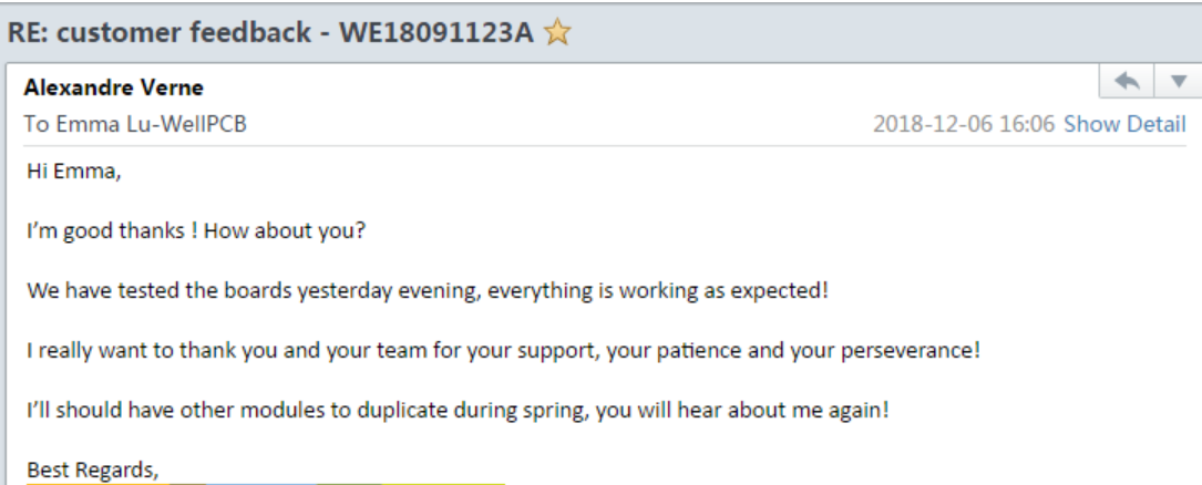
NXP France
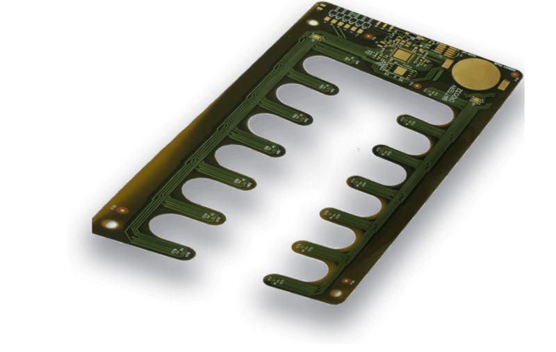
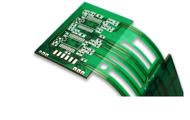
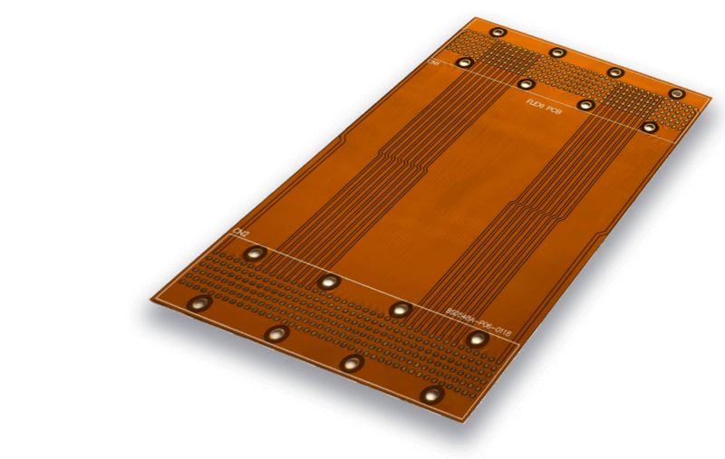
Products Show