Contents
Circuit Example of a Mosquito Swatter Bat
Our first basic concept involves using electrocuting equipment that is both fun and clean.
Circuit Diagram
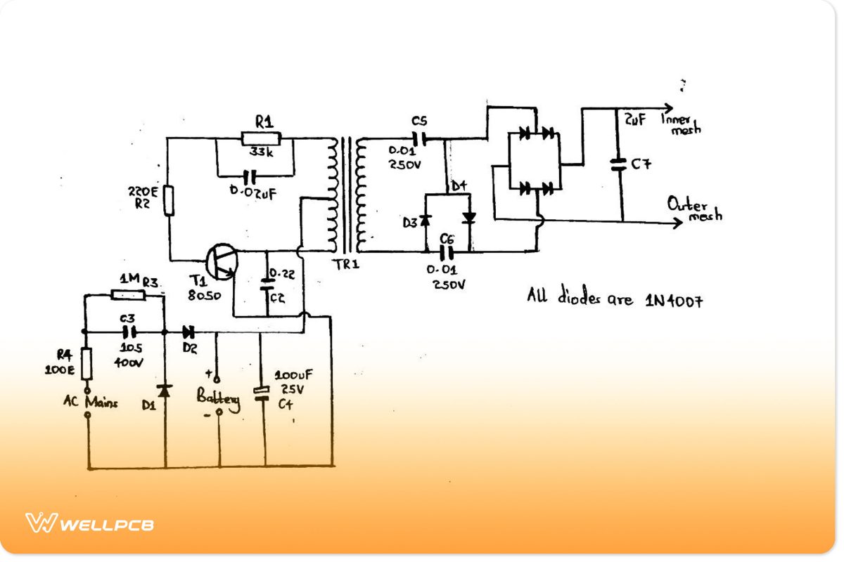
A basic circuit diagram of a mosquito swatter bat
How the Circuit Functions
- C1 and R1 plus the preset determine the oscillation frequency.
- Then, we have TR1 built from an EE type of ferrite core, forming a small ferrite core transformer.
- The circuit is compatible with a 3V battery pack (DC supply) that you construct by placing some AAA cells in series.
- If you apply power to the circuit, the center-tapped transformer and transistor oscillate at the recommended high frequency. Consequently, the battery current passes crossway through the TR1 secondary output winding in a push-pull manner, generating high output voltage (about 200V) at the winding.
- Additionally, you can use a Crockcroft-Walted ladder network at TR1 output to raise the voltage further (to about 600V).
- Afterward, the 2uF/1KV capacitor steps it up and stores the high-voltage energy without discharge. The voltage then undergoes rectification and goes into the bridge rectifier for further rectification.
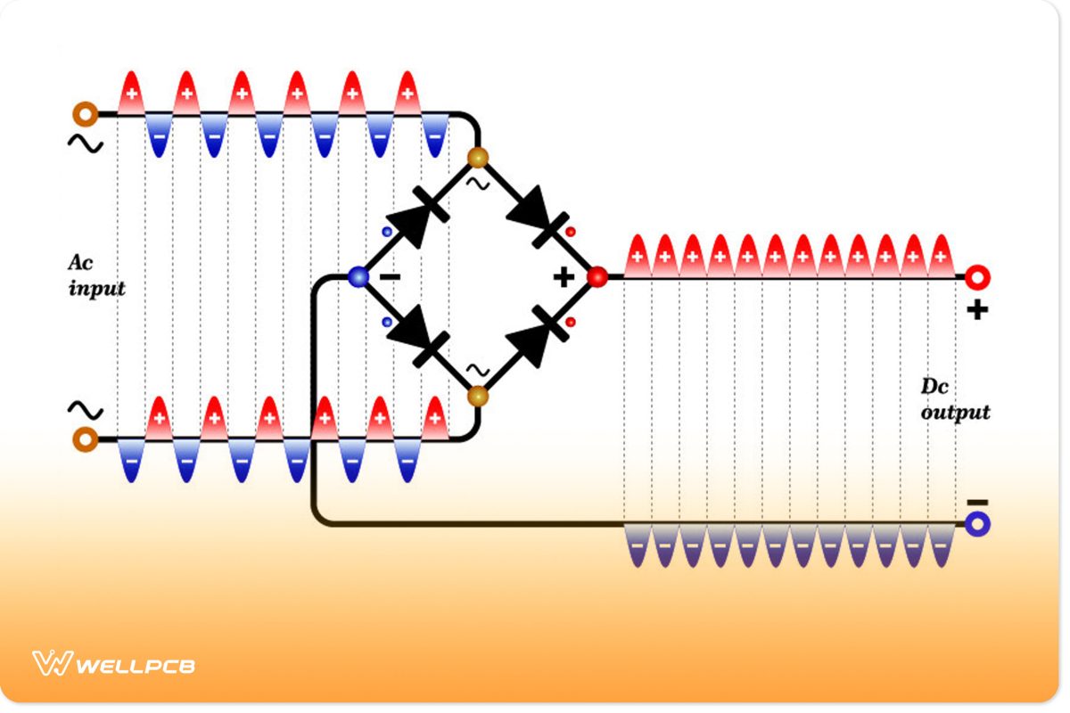
(bridge rectifiers operation)
- Bringing the output terminals of the 2uF capacitor closer together causes the electric power in the capacitor to break down the air barrier. The capacitor’s electric current will then arc across the terminal gap as a flying spark.
- Consequently, it’ll stop until the capacitor recharges enough to produce another spark.
- Apply this circuit on a mosquito swatter,r but remember to;
- Connect or tie the 2uF capacitor’s end terminals across the external and internal bat mesh layers.
- Weave and tightly position the metal mesh layers over a solid plastic frame at a distance from each other to prevent sparking.
- Finally, if a mosquito flies over, the swatter bridges it between the metal meshes, and the high voltage emission conduction follows. It instantly kills the insect with the spark.
Making the Ferrite Core Transformer
Our mosquito zapper above also has a transformerless charger circuit.
You can use it to charge the 3V rechargeable battery by connecting it to the main supply during insufficient power generation.
Circuit Example of a Commercial Mosquito Zapper
Let’s now discuss the second commercially designed mosquito racket.
Circuit Diagram
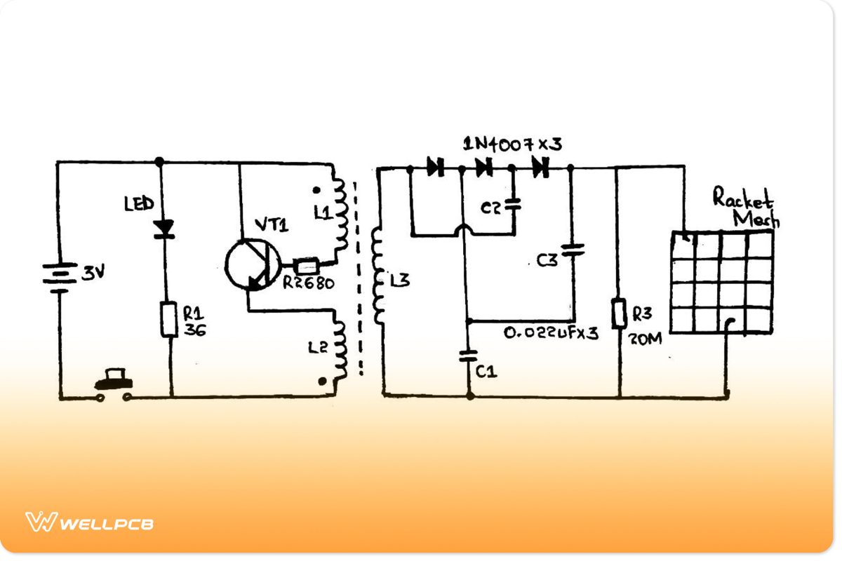
Circuit diagram of a mosquito zapper
How the Circuit Functions
- Pressing the power switch SA energizes the high-frequency oscillator with a step-up transformer T and transistor VT1. The power supply is often from a 3V Direct current with a boost from T to about 500V.
- Then, the ladder network with capacitors C1-C3 and three 1N4007 diodes steps up the high-voltage 500V range to about 1500V. The high-voltage PPC capacitor then stores the voltage.
- Next, the 1500V terminates in the mosquito racket net, whereby it can electrocute a closely nearby mosquito.
- Lastly, use an LED to monitor battery power life and display the off/on circuit state. A tweakable series resistor R1 is ideal for improving battery life.
Component selection
Some of the essential electronic components needed include PPC-type
- PPC type capacitors (minimum of 630V),
- Resistor (1/4W or 1/8 W),
- Diodes (1N4007) or FR107/BA159,
- LED (3mm tiny 20mA), or
- 2N5609 oscillator transistor (alternatively use Bipolar transistors D880 or 2N2222).
Building the High Voltage Transformer
- You will first need a 2E19-type ferrite core with a matching plastic bobbin.
- L1 comprises a magnet wire with about 22 turns or an enameled copper wire of φ0.22mm. Contrarily, L2 has around eight turns of magnet wire but a similar φ0.22mm enameled copper wire.
- Lastly, we have L3, which consists of a secondary winding of round 1400 metal tuns and an enameled copper wire of φ0.08mm.
Caution: Our circuit design above does not isolate from the mains input voltage, which means it will contain lethal mains AC voltage. Therefore, handle and test the circuit with extreme caution when powering it.
How to Build a Portable Bug Zapper
Generally, designing a bug zapper depends on its design, size, and types of bugs targeted.
Materials needed
- Blacklight/ a UV LED light bulb,
- Handsaw,
- Glue gun,
- Drill,
- Stapler wire,
- Soldering gun,
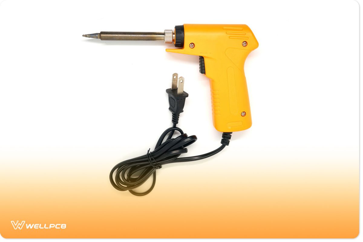
- Screws,
- Plywood,
- A 1-yard squared 1/4” mesh wire/grid,
- Six long wooden dowels
- Two garden plant vase dishes,
- A new 6V rechargeable sealed lead acid battery and
- Circuitry from an old rechargeable lantern.
Steps
- Make the bug zapper’s foundation.
First, build a round wooden base plate with a similar diameter to the inside of a plant vase cover. Then, tighten the wooden base plates with vase covers by drilling their sides.
Next, equally, drill about six holes in the wooden base plates.
After, place the dowels in the holes to strengthen the frame and ensure insulation between the meshwork.
Make a cylindrical shape out of the mesh while ensuring they don’t touch while overlapping. Use a spade bit to make a light-fitting hole at the plate’s center.
- Fit the zapper LED bulb/blacklight; electrically fit the bulb and hot glue it.

(UV purple blacklight)
- Electrify the mesh gride; First, solder in the red and black wires near the top surface of the mesh. Afterward, use the soldering gun to weld any overlapping metal mesh.
- Add the component of the bug zapper. Here, you can wire or glue the circuit boards, battery, and lantern components into their stipulated areas on the bug zapper.
- Take the lantern’s carrying handle and reuse it for the zapper. Later, drill a hole in the endcap before mounting the power cord, LEDs, switch,h, and handle.
- Finally, glue everything in place.
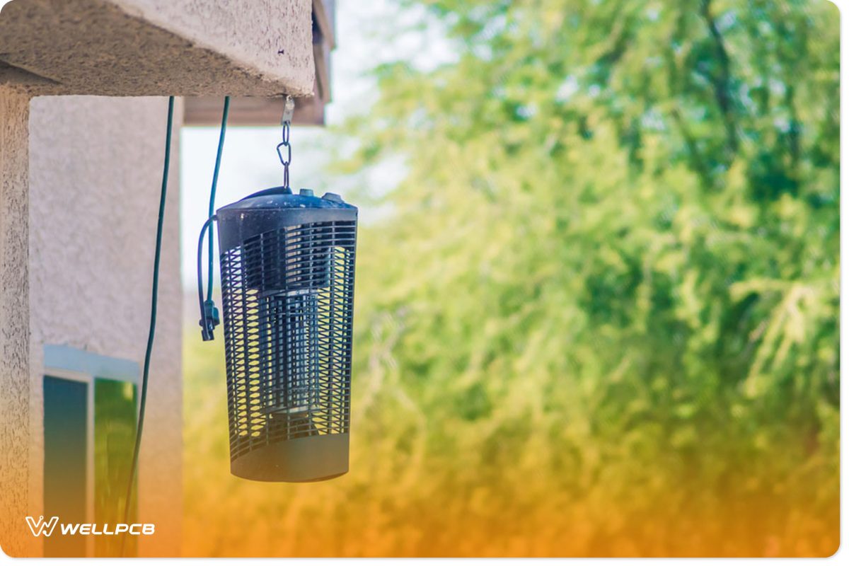
(a complete bug zapper)
Conclusion
We hope you’ll find the above guidelines easy to comprehend and follow in your electronic systems.
For more information, you can reach out to us. We’ll be thrilled to help.


