Contents
The Working Principle of the Buzzer Circuit
Buzzers are sound devices that can convert audio signals into sound signals. Buzzers are more like simple circuits powered by direct current (DC). Also, you can use it for different applications like alarms, printers, computers, and other electronic products that produce chime sounds.
Furthermore, the buzzer has two main types, which include the electromagnetic buzzer and the piezoelectric buzzer. So, to explain the working principle of the buzzer circuit, we’ll discuss the two types separately.
The Working Principle of the Piezoelectric Buzzer Circuit
The piezo buzzer utilizes ceramics with the piezoelectric effect to generate pulses. These pulses create a current that uses the vibrations of a metal plate to create buzzer tones.
The main components of this buzzer include the resonance box, piezoelectric plate, housing, and impedance matcher. Plus, you may find some piezoelectric buzzers with diodes that emit light.
Additionally, the multi-resonator components work with transistors or ICs (integrated circuits). Hence, when you switch on the power supply of this circuit, which is usually 1.5 – 2.5 DC voltage, an oscillation occurs. As a result, the multi-resonator generates an audio signal of 1.5 – 2.5 kHz as its output. At this point, the impedance matcher will get to work.
That is, the matcher will move the piezoelectric plate to create sound signals. Also, manufacturers produce most piezoelectric plates with lead magnesium niobate or zirconate titanate piezoelectric ceramic. Plus, silver electrodes surround both sides of the ceramic.
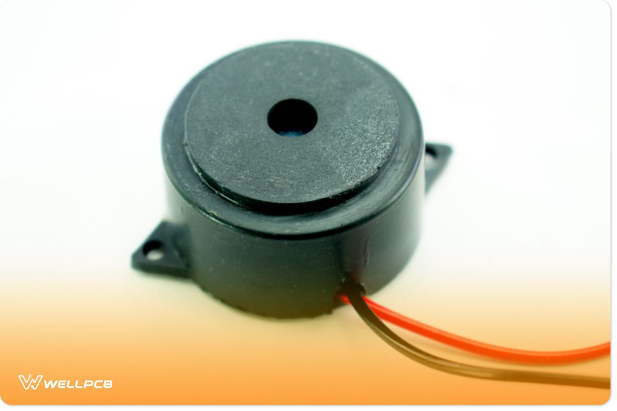
Piezo Buzzer
The Working Principle of the Electromagnetic Buzzer Circuit
On the other hand, the magnetic buzzer has an oscillator, vibration diaphragm, solenoid coil, housing, and magnet as its major components. When you switch on the power supply of this magnetic buzzer circuit, the oscillator generates an audio signal and sends it through the solenoid coil to create a magnetic field.
Interestingly, this is where the vibration diaphragm comes in. This component vibrates periodically and makes sounds based on the actions of the magnet and the solenoid coil. Thus, the magnetic buzzer generates an output of 2 – 4 kHz.
The electronic circuit is perfect for applications in music and voice because it has a great sound.
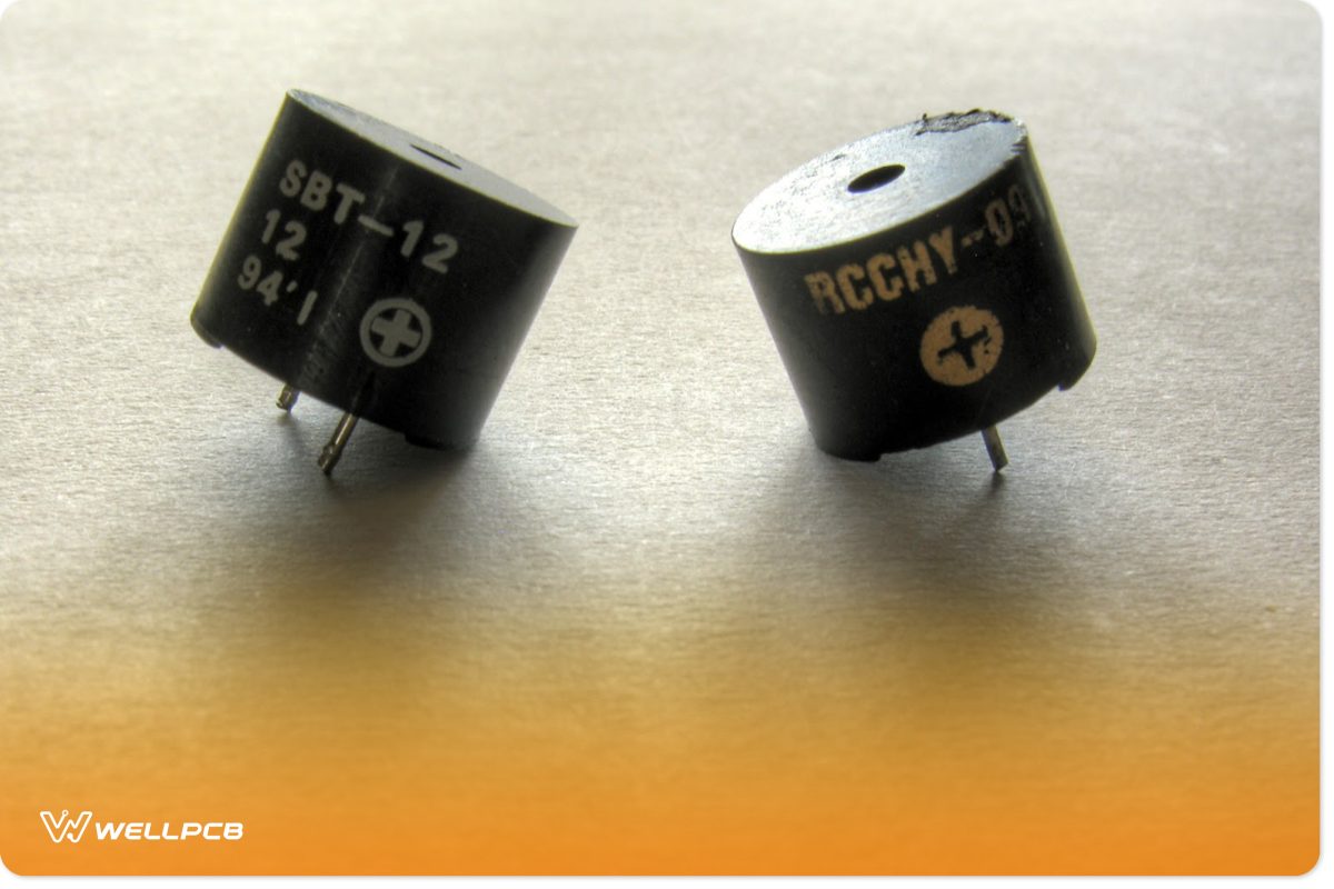
Electromagnetic Buzzer
Apart from the piezo and magnetic buzzer, there’s also the active and passive buzzer circuit. Active buzzers have oscillators and generate sounds when energized. It works by converting direct current into pulse signals, usually at a particular frequency.
However, passive buzzers don’t use oscillators and DC signals to make a sound. But you can drive it with a 2k – 5k square wave because of its constant magnetic circuit.
Component Selection of a Buzzer Circuit
The buzzer circuit has a large working current, and you need to drive it with an amplifier circuit. So, the buzzer circuit generally includes the following components:
Buzzer
Five things become essential when you apply passive buzzers (square wave) or active buzzers (DC voltage) at both ends of your sounding element. They are the shape dimension, working current, sound direction, driving mode, and working frequency. Plus, you can choose the parameter you want based on what you need.
Freewheeling Diode
Buzzers are inductive elements. Hence, you can’t change its current. However, you can use a freewheeling diode to monitor the continuous current consistently. Otherwise, you might damage the driving triode—which may crash the entire circuit system. How? Without the freewheeling diode, the buzzer circuit can generate a high spike of tens of volts.
Filter Capacitor
This component helps filter the buzzer current’s influence on other parts of the circuit and improves the AC power supply.
Triode
When the base gets high, the triode becomes saturated. As a result, the buzzer will generate sounds. However, when the base gets low, the triode enters a closed state. Thus, it terminates the sounds.
How to Make a Buzzer Circuit
Now, here’s an example of a simple circuit that utilizes a NE555 timer integrated circuit as well as a speaker and a variable resistor-capacitor network.
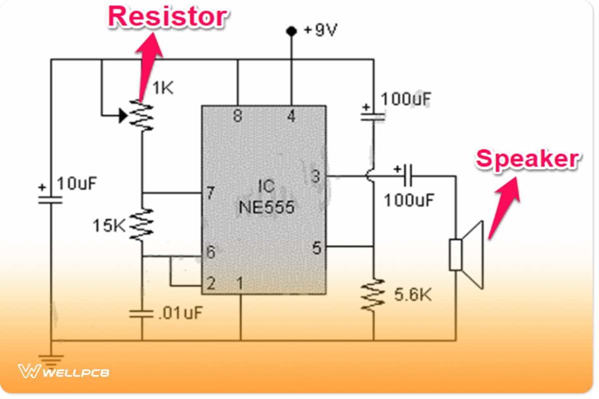
Simple Buzzer Circuit
Circuit Components
Here is a list of the components required for this circuit:
- Breadboard (1)
- 555 Timer IC (1)
- 9v Battery (1)
- Speaker (8 ohms) (1)
- 15k resistor (1)
- 5.6k resistor (1)
- Connecting wire (1)
- 0.1uF capacitor (1)
- 100uF capacitors (2)
- 1k variable resistor (1)
Instructions
Let’s look at how to create this basic circuit in 5 simple steps:
Step 1: Assembly
The most important part of this circuit is the IC555 because it controls everything. So, the first thing you need to do is attach the 555 timer IC to the middle of your board.
Next, you need to connect your capacitors. The first 0.1uf capacitor goes in between pins 1 and 2. While you’re at it, ensure that you place the side in the direction of pin 1. Also, you have to attach the other 100uF capacitors near the speaker of the circuit.
Then, use your wires to connect pins 2 and 6 to the gaps in the power supply row of your breadboard.
Afterward, connect the 15k resistor between pins 6 and 7. Also, you can place the 1k variable resistor (between pins 7 and 8) while you connect the last 5.6k resistor (between pins 1 and 5).
Step 2: Connect the speaker (buzzer)
For this circuit, the speaker acts as our buzzer. Thus, you can connect pin 3 to the positive wire of the speaker.
Step 3: Power up the IC555
In this step, you need to connect pin 1 to the ground and pin 8 to the positive side of your breadboard.
Step 4: Connect the battery.
First, connect the positive wire to the positive row of the breadboard and the negative wire to the negative row. After this, you can connect your battery to power up your circuit. While you’re it, place the capacitor parallel to the battery.
Step 5: Test and Troubleshoot
Now you have a complete buzzer circuit. Make sure you test it to see if you have the right connections before making the final assembly.
How to Add Buzzer Loudness in the Buzzer Circuit
Adding loudness to your buzzer circuit is not a complex process. It simply involves making a ring circuit that creates a series of general bell sounds. The best part is that you can use transistors to make an easy and cheap buzzer circuit. Here’s a circuit diagram to help you understand better:
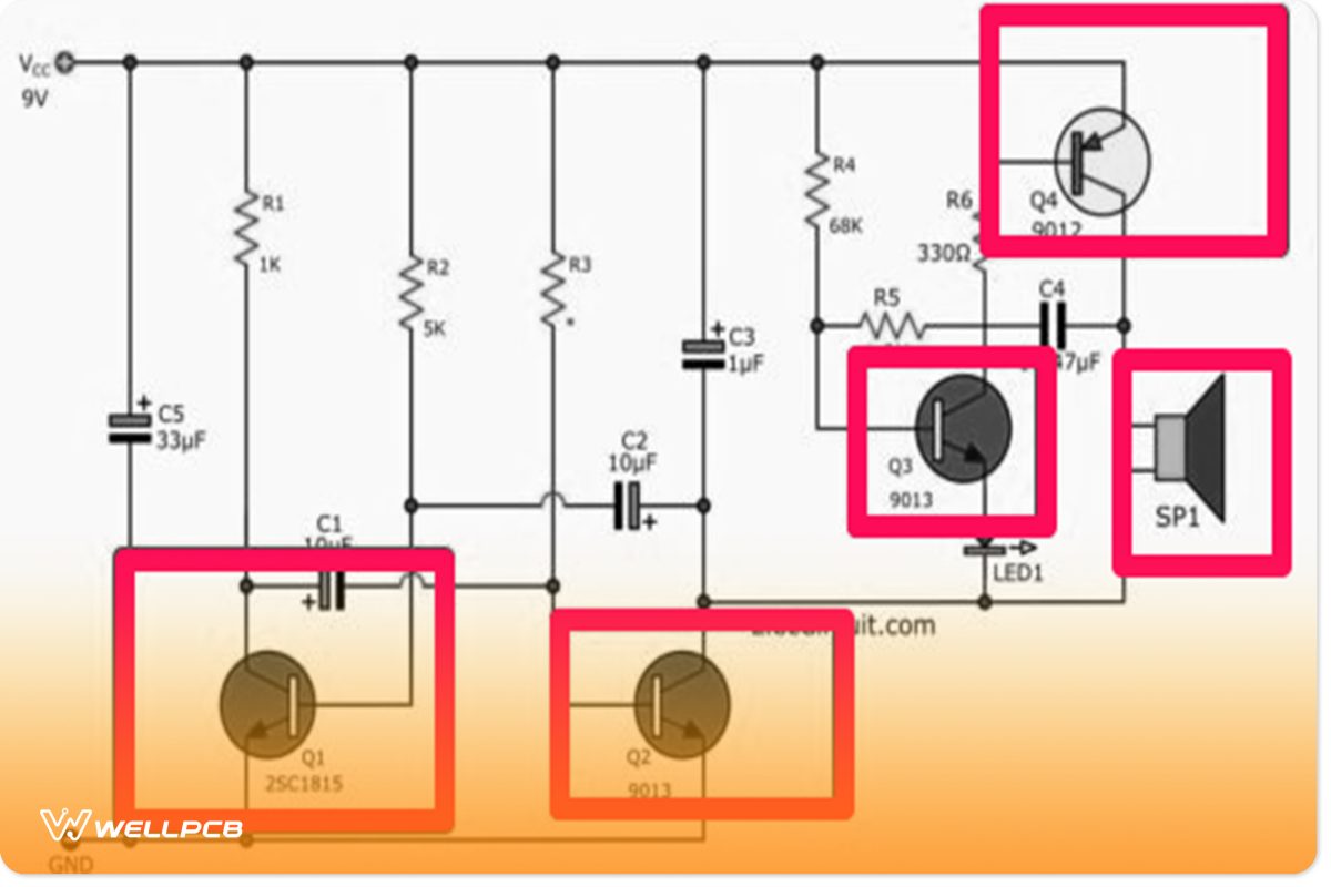
Ring Circuit
Components Required
- (6) Resistors (1k, 5k, 2.7k, 68k, 1.2k, and 330 ohms)
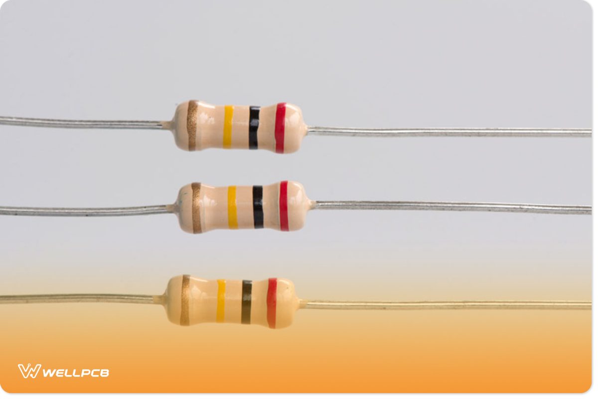
A Set of Resistors
- (3) Semiconductors (q1, q2, and q3)\

Integrated Semiconductors
- (4) Electrolytic capacitors (c1, c2 (10uF 16V, c3: 1uF 16v)
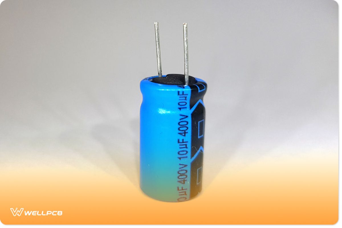
Isolated electrolytic capacitors
- (1) Ceramic capacitors c4- 0.047uf, 50v
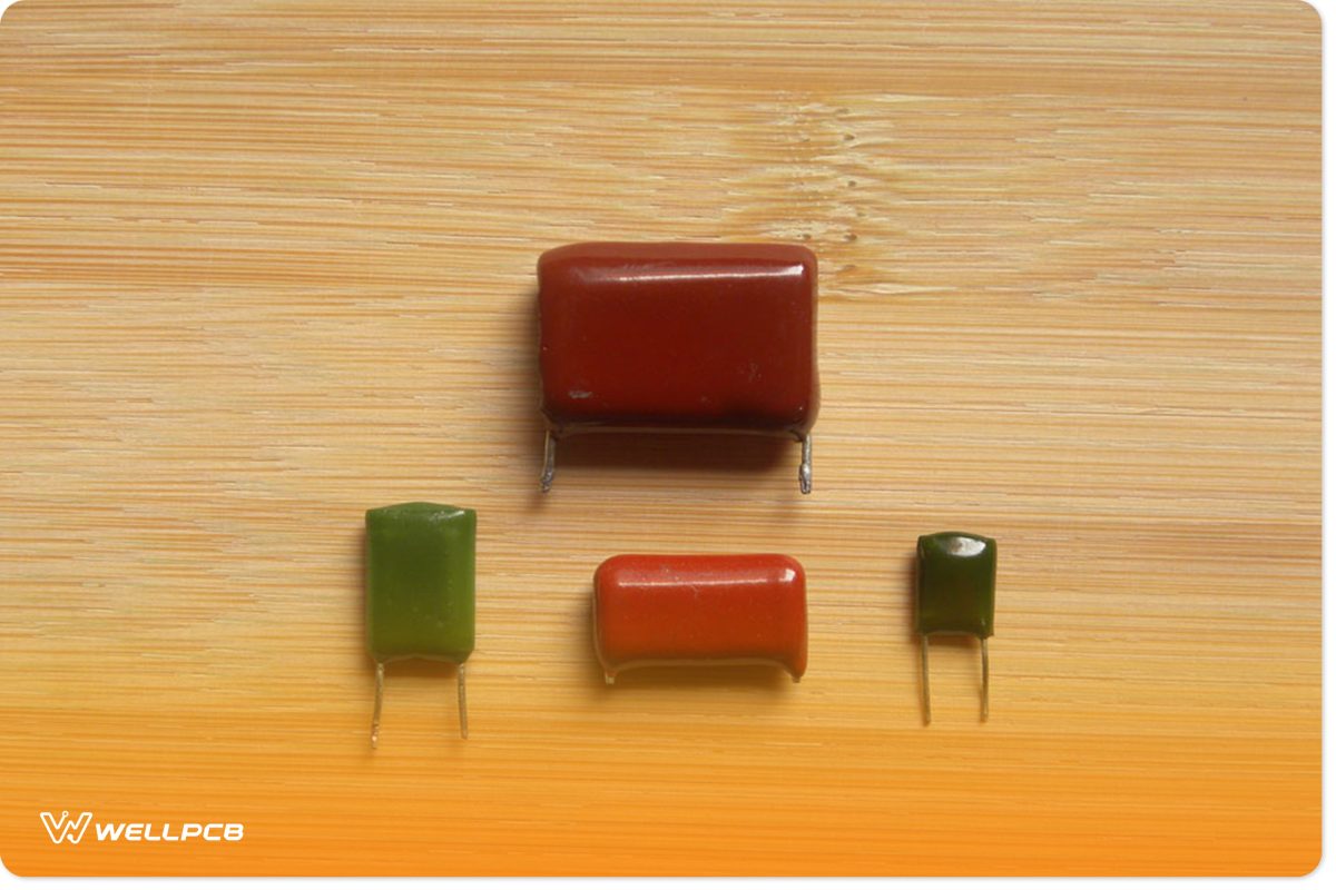
Colorful ceramic capacitors
- (1) LED (any color)
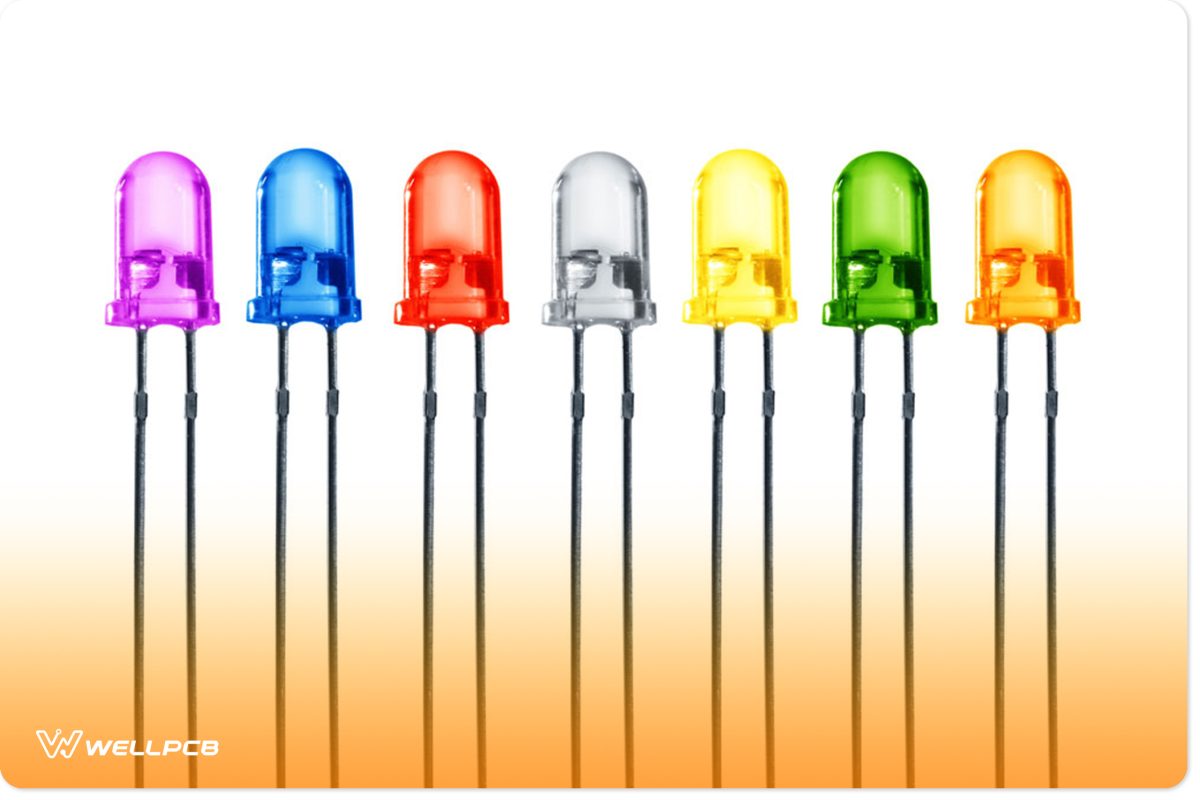
Seven LED color
- (1) Speaker (8 ohms)
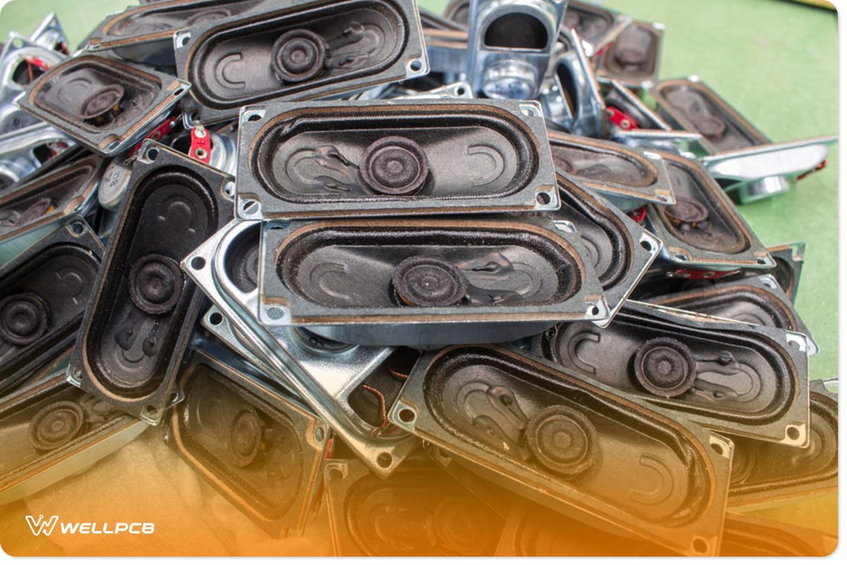
8 Ohms Speakers
Instructions
It will help if you get a 9v operating voltage for this circuit to work. Also, you only need a few components to piece this project together. So, you can assemble these components on the universal PCB or make a simple DIY PCB.
Lastly, you can wire up the circuit and various components. But, it’s crucial to watch out for the polarity of electrolytic capacitors. While you’re at it, ensure you place the transistor pins correctly.
Final Words
Despite the many types and specifications of the buzzer circuit, you can always select the buzzer you desire according to major parameters like driving mode, voltage, square wave, or fixing mode. Plus, you can also make selections according to the required sound pressure or frequency.
Well, that’s everything you need to know about the buzzer circuit. If you need more information about this circuit, feel free to contact us.


