Contents
What are Digital Buffers?
A digital buffer, otherwise called a voltage buffer, serves as an electronic circuit element. Generally, it isolates both the input and output sources from each other. During the isolation process, a voltage buffer applies voltage matching its input voltage. It could also subtract voltage from the circuit. As a result, minimal current flows through it without interfering with the main circuit, keeping it safe from damage. Typically, these require a low voltage level, ideal at 0V or 5V.

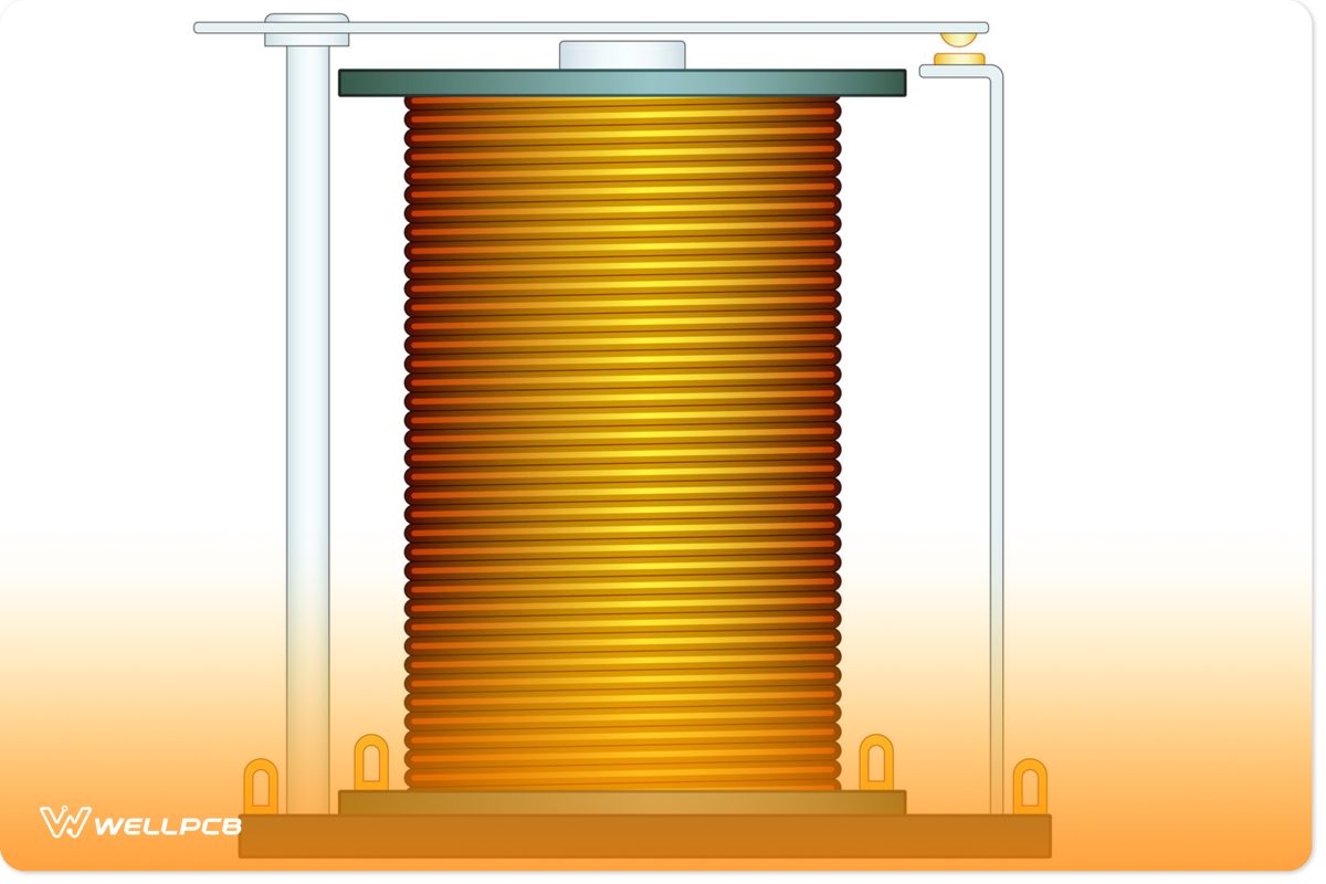
(Image showing a relay)
Moreover, this helps prevent the signal source from changing through loads, such as lamps, relays, and solenoids. Digital buffers also provide on-and-off data transmission control capabilities for common applications like registers, flip flops, and bus drivers, making them extremely important. These consist of output terminals that deliver a high or low signal, relying on its input value.
Why Should We Use a Digital Buffer?

(A digital buffer transfers voltage from one circuit to the next.)
Digital buffers transmit voltage from a high output impedance to the second circuit with a low input impedance. This will prevent the high impedance from disrupting the main circuit. Additionally, it boosts current capacity, making switch transistors operate more efficiently.
Types of Digital Buffers
Currently, two main digital buffers exist: a single input voltage buffer and a tri-state digital buffer.
Single Input Voltage Buffer
Single-input voltage buffers do not perform input signal inversion or modifications. Two types exist inverting buffer and non-inverting buffer.
Inverting Buffer
An inverting buffer configures of a state opposite to the input source. For example, it will set the input to high if the output is set to low. Common applications for an inverter include state machines, decoders, and various other digital devices.
Non-inverting Buffer
As the name suggests, a non-inverting buffer does not perform an inversion. In this instance, its input will draw in HIGH or LOW voltage and output its value. The input determines whether or not the output terminal delivers a HIGH or LOW value. In this condition, the output sets to as high long as the input sets.
Tri-State Digital Buffer
The Tri-state Buffer, which serves as an input control switch, electronically cuts off the output from the input circuit. This occurs through its enabled signal input pin or external control. In effect, the control signal acts as a logic 0 or logic 1 signal, putting the Tri-state Buffer in a state where the output performs normally. It may also enter another state that disconnects or blocks its output.
Then, the output shuts off while in the third state, causing the circuit to open. As a result, the output is not set too high or low. Instead, it produces a high impedance, called HIGH-Z or HI-Z, unresponsive to the input signal. In effect, the current from the supply remains blocked out.
We also detailed the three types of tri-state digital buffers below:
Active High Tri-State Digital Buffer
The output pin will connect to the input pin after applying a high positive signal to the enable pin. This triggers the active high tri-state buffer.
Applying a low or negative signal to the enable pin causes the output to disconnect from the input. Afterward, it sets to the HI-Z state, forcing the output to remain unresponsive to the input. Meanwhile, the output configures to an open circuit condition.
Active Low Tri-State Digital Buffer
In the active low tri-state buffer, the output connects to the input. Moreover, this occurs after applying a low or negative signal to the enable pin. However, applying a high or positive signal to the enable pin provides a different effect. That’s because it causes the output to disconnect from the input. Then, the output enters an open circuit condition while remaining in a HI-Z state.
Inverting Tri-State Digital Buffer
During the active tri-state buffer, the gate and enable pin function as a logic NOT gate. Applying a high or positive signal to the enable pin causes it to activate. From there, it will operate similarly to a normal logic gate. This condition causes the output to inverse with the input. If the enable pin receives a low or negative signal, the output will be configured to an open circuit or HI-Z.
What is the Purpose of a Buffer Gate?
A buffer gate’s role involves performing signal amplification on a circuit. It achieves this by improving a weak signal’s current capacity and providing it with load-driving capabilities. Generally, buffer circuits contain a triangle without an inverter bubble on the output terminal. Buffers may also form on the open collector output. Analog signals, such as sensors, can connect to digital inputs via its gate.
What is the Difference Between Buffer and Inverter
An inverter performs the inversion process of a circuit’s input signal with the output. For example, it sets the output to HIGH when the input is configured to LOW. And, it will force the output to LOW when the input sets to HIGH. Meanwhile, the buffer slightly improves the signal’s strength.
Applications of Digital Buffer
Control circuits: Useful for subways, aircraft, and manufacturing processes.

(Digital buffers are common in subways)
Temperature measurement circuits: Examples of temperature measurement circuits include boilers and airplanes flying in a cold area.

(Boilers contain a digital buffer to measure the temperatures)
Strain gauge circuits: These measure defects found in aircraft wings, bridges, and a building’s I-beam.

(A digital buffer can help measure defects found in airplane wings.)
Summary
Overall, a voltage buffer transfers voltage from a high impedance to another circuit with a low impedance. Additionally, it will strengthen the circuit’s signal via amplification. One of the main purposes involves isolating the circuit’s input and output sources from each other. In effect, the voltage decreases or matches the input. Achieving this allows minimal current to flow through while protecting the main circuit. Moreover, digital buffers are crucial for registers because they provide on-off data transfer control capabilities.
Do you have any questions regarding digital buggers? Feel free to contact us!


