Contents
Eagle PCB Design Software
1.1 Definition
The Eagle software is designers used as an abbreviation for Easily Applicable Graphical Layout Editor (EAGLE). As stated earlier, the Eagle design software is coming up with the PCB.
This process is carried out before it is manufactured, and thus, it is mainly done through the computer.
It is award-winning software that has a user-friendly interface and is affordable for many designers.
Many designers look for this software because of its usefulness and uniqueness.
1.2 Features
The software has some features that make it preferable for use as compared to the rest. It contains a schematic editor that is useful for the construction of circuit diagrams.
The software can run on anything, including Windows and Mac.
It is also low on capacity as it can take a maximum of 200 MB with an installer of 25 MB. It comes with both freeware and low-cost ware that can design any PCB.
We can sum up the best features of this software as follows:
- Creation of professional PCB designs.
- Creation of boards just by a click of the mouse.
- It allows up to 999 sheets to support complex designs that most designers may love to use.
- Allows for the arrangement of sheets by the drag and drop method.
- It helps to manage different assembly variants.
- It is an easy-to-use tool with complex functions for all types of designers.
- Has a particular capability of performing a design rule check to ensure that all the connections are made correctly.
1.3 Usage
The software allows improvement of features that may include import/export of data and simulation, among many other commands. The Software can be used on most operating systems, including the following:
- Windows
- Linux
- Mac
How To Install And Set Up
2.1 The software
PCBs are essential for making all the parts of the circuit work effectively. The Eagle PCB design software, in particular, is the most preferred for designing PCBs and this is because of the following reasons:
- It is lightweight. As mentioned earlier, the software can occupy a space of up to 200 MB, which is entirely negligible compared to the functions and advantages it brings along with it.
- It is cost-effective. The software exists in both the freeware version and the low-cost paid version. Even with the freeware version, there is still a range of functions that you can achieve regarding Eagle PCB design software that can run on a wide range of operating systems, including Mac and Windows.
2.2 Download, Install, and Run
Cadsoft is the developer of this software, and you can, therefore, download it from their site. There you can get the most suitable version for your operating system.
The download is also quite light, as mentioned earlier, and thus, you will not spend so much of your space on it.
Like any other program, the Eagle PCB design software installs easily on your computer to ensure a seamless user experience. It first extracts itself without any command from your side, and then you would have to configure the installation through its various series of dialogs.
During the setup, you will encounter a window that usually comes in the last stage of the installation process. The window is as shown below:
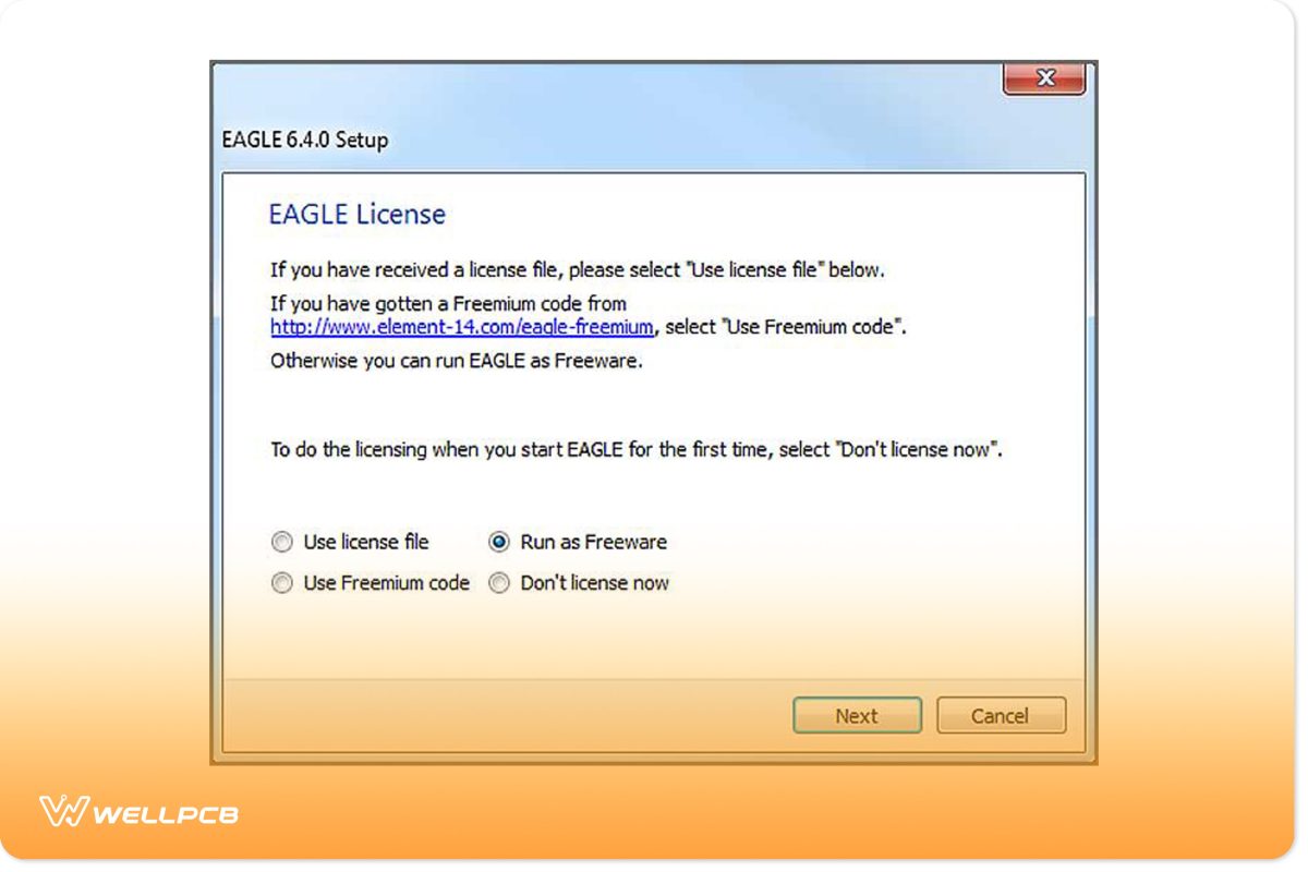
The good thing about the software is that you can either use the paid version or use it for free, as you see above in the options.
- It is supported only by email and forums.
- It is meant for designers who are either using it as a training ground or just for personal use as it is non-profit. You can, therefore, not use the freeware version for profit-making or selling.
- The freeware version only has two signal layers that are permitted. If you want more layers, then you can probably think of taking the licensed option that is paid for.
- There is a limitation on the size of the PCB design concerning dimensions when you are using the freeware version.
In general, you will have the freedom to use most of the application’s functions, save for a few limitations that you will encounter. If you want more functions, you can consider licensing the software, which is still cheaper than the other.
When you run the Eagle PCB design software, you will first see a control panel, your guide to using the software.
- Design rules. These are a set of rules that your board design must meet before sending it off.
- Scripts. to customize the Eagle user interface. Here you can change things like the color schemes to your preferences.
- Projects. Here, all the projects that you have been working on are grouped.
- CAM jobs. The CAM processor opens these to help in the creation of Gerber files.
- User Language Programs (ULP). These are scripts that are written in the Eagle user language.
- Libraries. The libraries help store parts, and they contain a group of parts that are firmly related to each other.
To check out more details about the above, you can look at the following link: https://learn.sparkfun.com/tutorials/how-to-install-and-setup-eagle
Eagle PCB Design Full Version Free Download Crack
3.1 About
The Eagle PCB design software has easy-to-use and practical tools that any designer can use. It doesn’t mean that it cannot perform complex works either. It is also useful for profound works that require a lot of concentration and tools.
3.2 Eagle PCB design software full version free download crack
The software can easily be downloaded from the developer’s site.
The site is known as Cad soft and has up-to-date software that matches that of your processor.
The software extracts itself through the inbuilt mechanism that has made it, and then it presents a way of setting up the installation. The software has both the freeware version and the licensed one.
The freeware version has most of the tools that you would need to save for a few limitations that may hinder your usage, including a non-profit limitation that ensures you cannot use the software for commercial purposes.
You can consider going for the licensed version of the software as it is limitless. Again the price you would pay for it is quite insignificant in a way that you wouldn’t feel the pinch that much.
The licensed version is more effective and cheaper than the other software present in the market. The Eagle PCB software crack can create different sizes and multilayer printed circuits.
The user software allows you to copy or even erase the items that have been selected, place the contents of the clipboard, and pick from a variety of components that can be placed in the environment in which one is working.
The Cadsoft Eagle PCB software full version crack is easy to use and is also quite cost-effective. It is a brilliant way to design printed circuit boards.
- It has a modular design block.
- Reduces complaints about component availability.
- Operates at full speed.
- It has a modular design block.
- Make sure that the motherboard is ready.
- It enables creativity through off-the-shelf widget libraries.
- Enables you to integrate your PCB according to the way you would want effectively.
- It helps to bring your design to life with the layout tools.
How To Make A Design On Eagle Software
4.1 Making a PCB design using the Eagle software
A printed circuit board, commonly known as a PCB, is a board made up of some electrical components connected with the use of conductive electrical tracks.

PCBs are appropriate to use especially when you want to avoid some problems, noise, and distortion. To go commercial, you would need to use a proper circuit board that works effectively.
Here, you will learn how to design a PCB using the Eagle software. You can achieve this even in the comfort of your home. It is a step-by-step process that is easy to follow.
- Making the schematic of the design to use in the PCB.
- Drawing the layout for the Printed Circuit Board.
- Finally, making the board. This process has different ways to achieve.
In actualizing the procedure, you will use what is known as a CAD tool for making the design schematic to use in the PCB. Drawing the layout for the PCB will also require the CAD tool.
- Mentor Graphics PADS.
- Altium designer.
- Autodesk eagle.
- KiCad.
- Cadence.
- Eagle free.
- Standard.
- Eagle premium.
As you may already be aware, it is a freeware version that is not paid for. Eagle can use it to capture schematics and the layout of the Printed Circuit Board.
The Eagle standard and premium versions have more features in addition to the standard freeware version. These features include added schematic sheets together with more signal layers and board area.
Now getting to how to use the Eagle PCB design software, you will run it and get to the. You will thereafter click on the file and select a new project on which you will now work.
You can then rename the project by the name that you choose and get to work.
Right-click on the project and create a new schematic. This is the first step to achieving your design. A new schematic window appears with a blank space for working. Here, you can draw schematics for the design you choose.
4.2 Designing a schematic
With a schematic editor, you will be able to design your schematic for the PCB. You then need to add components to your schematic. This you can do by adding an option from the toolbar. When you do this, a new window appears.
The window opens with the new components that you can then choose from to add to your schematic. Instead of adding the IC directly, you can choose to add a component like Op-Amp, an 8-pin DIP.
After you have selected the component, which is an 8-pin DIP, you can now click on okay and place the component in the schematic sheet.
You will click on the sheet once to position the component and an optional right-click to rotate.
Thereafter you can click on the etc. Key so that you can go back to the component selection window. To complete the circuit.
- A quarter-watt resistor.
- A small buzzer.
- A square-type POT.
- A thermistor.
- A two-pin screw terminal.
- The +5 and GND symbols from the supplying library.
After you have placed all the components together, you need to rename them and mention their values. It would help if you named them in a manner that software can easily understand them.
The procedure that follows is using the net option from the side toolbar to make the connections. After you have made all the connections, the final schematic looks like the one below:
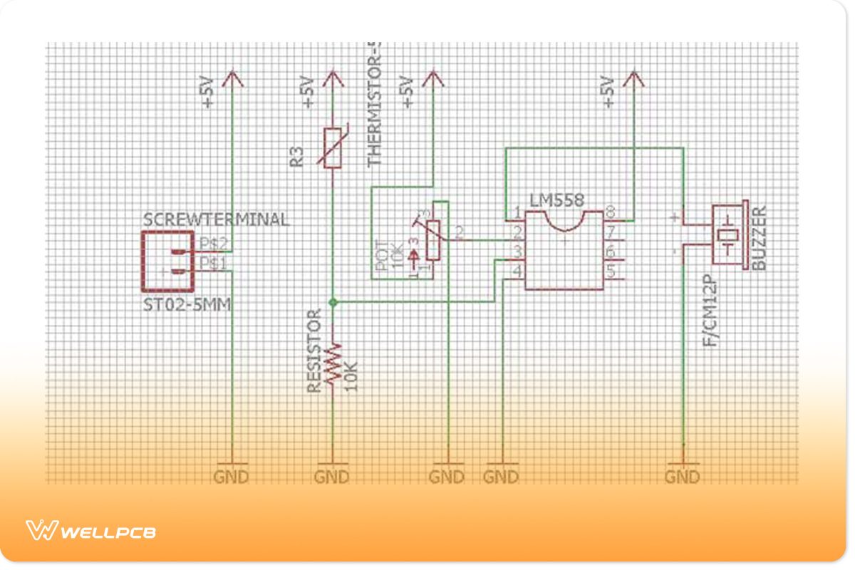
After you are done with the schematic, you can then proceed to design the PCB layout. You will do this using the PCB layout editor.
4.3 Generating PCB Gerber files
Gerber files are standard files that are used by Printed Circuit Boards (PCBs). They describe the PCB images and are usually inside a .rar or .zip archive.
Gerber files are used in the manufacturing process.
In the manufacture of PCBs, the Gerber files are required in RS-274-X format and can be generated by the use of some popular programs such as the following:
- Diptrace.
- Eagle.
- Circuit maker.
- Proteus.
- KiCad.
- Design Spark.
- PCBE.
Thus, we will look at how you can create Gerber files using this particular program. You can learn this at https://www.wellpcb.com/news/combining-multiple-eagle-pcbs-one.html.
The process of generating files in Eagle is quite straightforward. It is a straightforward process that doesn’t require much hustle and is easy to follow to the end. Other design software may be a bit harder to use as compared to the eagle.
In this process, open your design in, and here you find the CAM icon, which further brings the CAM processor.
In the new window, you need to open the CAM file by going to the file-open-job option, where you can locate the correct CAM file for your boards.
You should make sure that you are using the seed CAM file. You should then check by the use of the online Gerber viewer just before you confirm your order.
Conclusion
Eagle PCB software is, therefore, the best program that you can use to design Printed Circuit Boards before they are manufactured. The above was a guide on how to achieve the entire process, and in case of any inquiries and issues, you can contact us through the following:


