Contents
What is lm386 amp?
The LM386 is an integrated circuit featuring a low-voltage audio power amplifier. It delivers low-level voltage amplification for consumer applications. In that case, the gain sets to 20 without external components. But connecting a capacitor and resistor between pins 1 and 8 increases the gain’s value between 20 and 200. As a result, it drives an 8 Ohms speaker that has a 20 to 200 boost.
Additionally, the IC can run on a 9V battery since it consumes very little power. The LM386 also features an 8-pin DIP package. Each input pin connects to the ground, and meanwhile, the output biases to one-half the supply voltage.
Pin Description of lm386
We outlined the LM386 pin description below:
| PIN | Name | Description |
| 1 and 8 | Gain | These pins configure the IC’s gain through a connected capacitor. |
| 2 | Inverting input (IN-) | Amplifier’s inverting pin stays grounded. |
| 3 | The non-inverting input (IN+) | Non-inverting pin comes with the audio signal. |
| 4 | Ground | Ground pin connects to the system’s environment. |
| 5 | Vout | Vout connects to a speaker. It amplifies the audio. |
| 6 | Vss/Vcc | Links to a power source |
| 7 | Bypass | You can connect a decoupling capacitor via the bypass pin. |
Features and Specifications
You can also take a look at some of the features:
- Supply voltage: 4-15V
- Battery operation
- Maximum analog input voltage: 0.4V
- Maximum analog supply voltage: 18V
- Quiescent Power: 24mW @ 6V
- Voltage gain: 20 to 200
- Speaker impedance: 4 Ohms
- PSRR (Power Supply Rejection Ratio): 50dB
- Storage temperature range: -65°C to 150°C
- Operating temperature range: 0°C to 70°C
LM386 amp applications
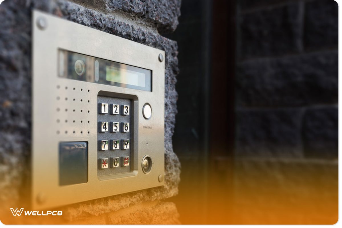
(An LM386 can provide clear sounds on an intercom.)
The most common LM386 applications include:
- AM and FM radio amplifiers
- Intercoms
- TV sound systems
- Low power audio amplifiers
- Small servo drivers
- Line drivers
- Ultrasonic drivers
- Power converters
- Power amplifiers
- Portable music player amplifiers
Application Circuits
We also included four circuit projects for the LM386:
Minimal LM386 Audio Amplifier
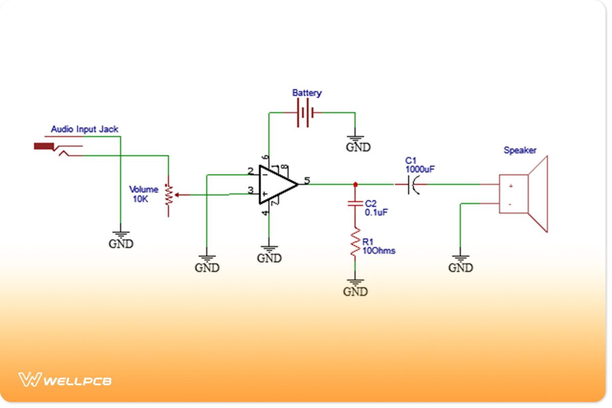
(Minimal LM386 audio amplifier circuit diagram.)
The above diagram shows the audio input ground passing through a similar direction as the audio output ground. Of course, this produces distortion, and then the amplifier will amplify that noise.
Additionally, you can connect the ground pin to the output, input, and power supply. As a result, it produces a much better sound even though you will probably hear some popping, static, and noise. Implementing two RC filters and two decoupling capacitors can solve this issue.
LM386 Amplifier with bass boost
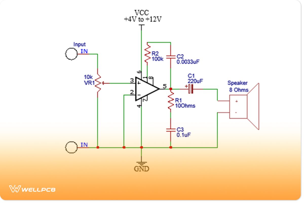
(Circuit diagram of an LM386 amplifier with bass boost.)
This circuit is capable of providing a bass boost. As you can see, R2 and C2 get connected in series to give a special bass effect. Also, the output gain relies on a bass frequency. In this case, a 25dB gain equates to 100Hz, and a 19dB gain equates to 2kHz.
You can also adjust the volume via VR1. Integrating R1 and C3 components helps to provide high-sound quality, and they enhance a high-frequency load, providing stability.
9V Power Amplifier using LM386
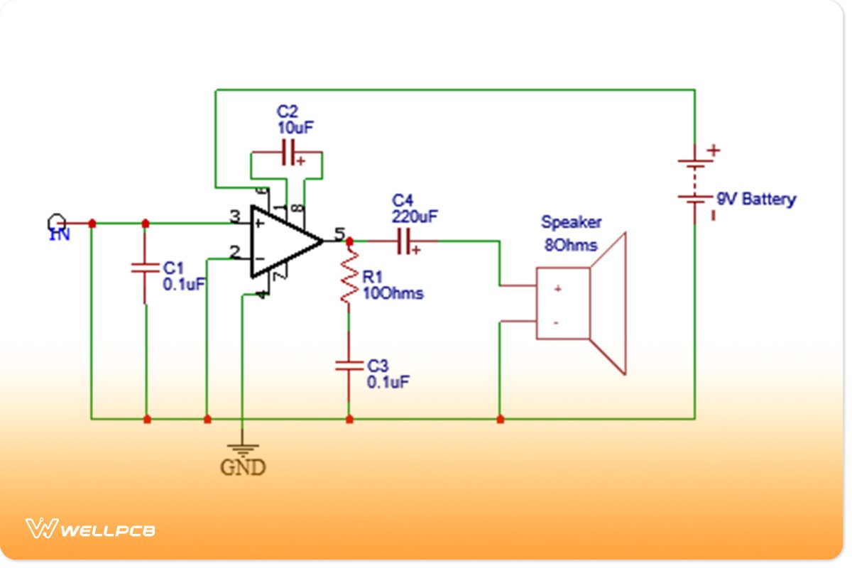
(9V power amplifier with LM386 circuit diagram.)
Next, we introduce a 9V power amplifier circuit. Generally, the signal transmits to input pin 3, which serves as a non-return phase from the signal amplifier.
The C1 capacitor stores noise, preventing it from damaging the input. C2 boosts the amplifier’s gain. Implementing a higher capacitance to C2 provides more income. However, this should be less than 100uF, and otherwise, it will produce distortion.
Additionally, LM386’s pin 5 represents the output. Meanwhile, C4 coupling strengthens the audio signals. Then, R1 and C3 get connected in series, which improves the high-frequency response.
LM386 Square Wave Oscillator
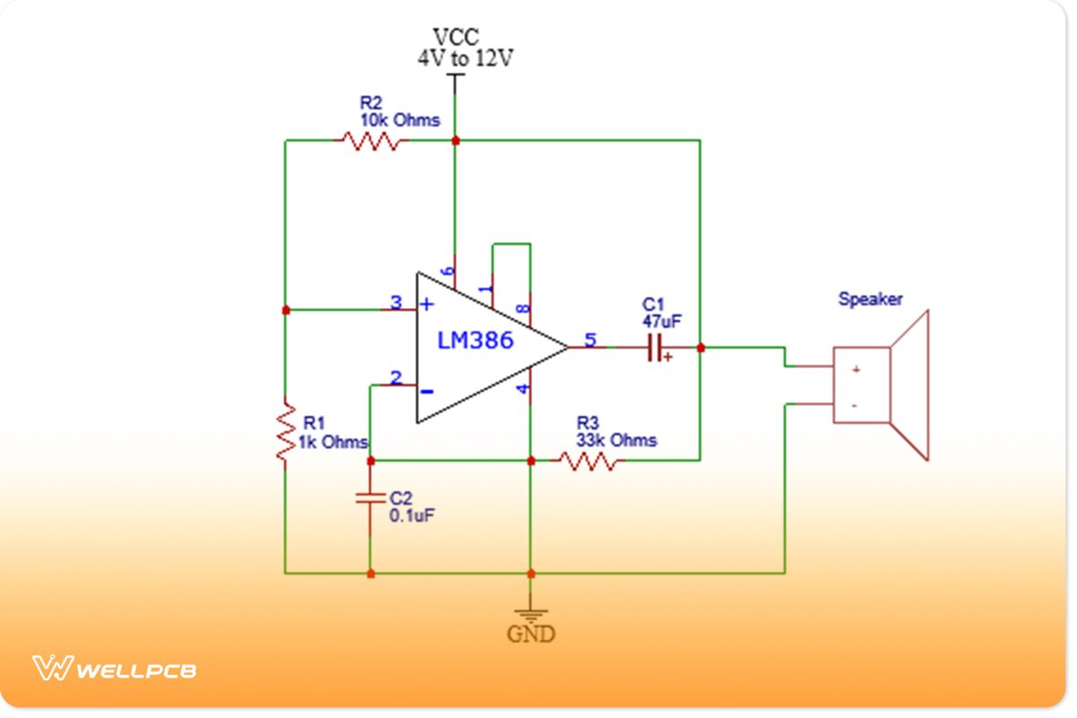
(Square wave oscillator circuit diagram.)
This diagram represents a square wave oscillator circuit, and it performs very similarly to an oscillator due to the IC op-amp integration. Additionally, the speaker features audible alarms. The output provides a frequency of 1KHz, and therefore, increasing C2’s capacitance results in a lowered frequency value.
Summary
Overall, the LM386 provides various advantages. For example, it helps to amplify sound for everyday devices. So if you own a music player, you will notice that it allows for a much cleaner sound. Additionally, this component can run on a low-voltage battery since it has a supply voltage rating of 6V. However, it will need a decoupling capacitor and resistor implementation to maximize efficiency. Thus, it will increase the gain level in any application that requires it, such as speakers.
Do you have any questions regarding the LM386? Feel free to contact us!


