Contents
LM324 Specifications
Here are the specifications for the LM324:
- You can configure the LM324’s unity gain by placing feedback resistors between the inverting (-) input and output pin.
- The LM324 has a maximum of 30v power supply range and a minimum of 3v.
- Also, the LM324 allows a maximum of 8 mA output current to flow from its positive supply to its output pin.
- You can get a maximum of 100,000 voltage gain on the LM324.
- Additionally, the LM324 uses only a 0.8 mA power supply current.
- Each op-amp at pin-output to the ground of the LM324 supports up to 20 mA output current.
LM324 Pinout
An LM324 chip has up to four operational amplifiers, each having two inputs and one output.
Here’s a brief description of the LM324 pinout:
- Pin 1 is amplifier A’s output pin
- Both Pin 2 and 3 are input pins for amplifier A
- Pin 4 is the positive supply voltage pin (VCC)
- Pin 5 and 6 are input pins for amplifier B
- The Pin 7 is amplifier B’s output pin
- Pin 8 is amplifier C’s output pin
- Both Pin 9 and 10 are input pins for amplifier C
- Pin 11 is the negative power supply voltage pin (GND)
- Pin 12 and 13 are input pins for amplifier D
- The Pin 14 is amplifier D’s output pin
Note: (+) on the pinout diagram indicates a non-inverting input, while (-) indicates an inverting input.
LM324 Output Voltage
The LM324’s output voltage range depends on the power supply voltage. For example, when you operate the LM324 from a 30V power supply, the output voltage swing would be around 26v.
But, when you operate at a 5V power supply, the LM324’s output voltage swing reduces to 3.48V.
LM324 Circuits Projects
As we mentioned earlier, there are several projects you can build with an LM324 circuit. Now, let’s look at some of these projects and give you what you need to make them.
LM324 Audio Amp
Here, we have a bass booster circuit that generates a low-pass filter for input audio. This low-pass filter generates a low input frequency while blocking high frequencies.
Interestingly, you can make this circuit with an LM324. However, this circuit only needs 2 of the LM324’s op-amps to operate.
Hence, follow the schematics below to build this circuit. Also, feed input to the course through pin two via a 47k resistor. Another 47K resistor should be connected between pins one and two.
Be sure to check the pinout diagram above if you’re not sure of these pins’ functions. Furthermore, this circuit requires you to connect pin four to a +9v power supply. Also, connect pin eleven to a -9v store.
We also recommend using a dual supply to operate this circuit. Why? Because it’s possible to adjust the frequency level with the RV1 (100K), you must connect all output to the amplifier’s input.

Circuit Diagram
Cricket Buzzer Generator Circuit using LM324
Normal buzzer sounds can get boring. Thankfully, you can make things more exciting with this LM321 circuit project. This circuit can turn your regular buzzer sounds into cricket singing sounds.
Here, the LM324 op-amp generates the cricket sound effects and emits them via a buzzer. Also, this circuit uses only three out of four op-amps on the LM324 chip while serving as a frequency generator.
Here’s how it works.
Op-amp 1/1 generates the tone at about 1400Hz to 15kHz frequency. Then, op-amp 1/2 releases up to 50Hz frequency, controlling op-amp 1/1. Then, it creates a tone similar to crickets. Finally, op-amp 1/3 generates about 2.2Hz to control the op-amp 1/1 and stops the cricket tone.

Circuit Diagram
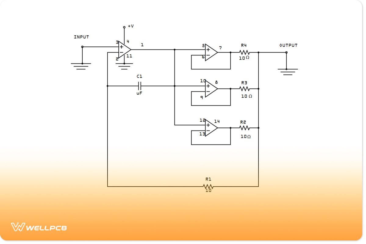
LM324 Amplifier Circuit
An LM324 IC works perfectly for amplification projects. For instance, you can increase the output current of your LM324.
If your LM324’s output current is low, you’ll have trouble using any circuit output. Thus, you can use the op-amp to increase the output current to a maximum of 85mA.
The LM324 will also work for various industrial, commercial, and military operations. Hence, you’d need an amplified output current if you plan to build any of those applications.
The LM324 IC has four op-amps, each dishing out an output current within the 20-40 mA range. So, applying the three op-amps in parallel space can increase the output current to 85mA. Plus, you’ll even get strong surge protection.

Circuit Diagram
Logic Digital Tester
A digital logic tester is one of the many projects you can build with an LM324. This circuit can use a potentiometer to adjust the right logic levels to indicate different thresholds.
The circuit uses LEDs to indicate different levels: LED1 (Green) for high, LED2 (Yellow) for medium, and LED3 (Red) for low.

Circuit Diagram
1.5v Battery Tester
Here’s another project example that uses the LM324 as a voltage checker. Interestingly, this circuit can measure the voltage of any AA or AAA 1.5v battery.
Also, the circuit displays its values on an easy-to-read LED display. Additionally, it can measure both plain and rechargeable batteries.

Circuit Diagram
Op-amp LED Flasher
This circuit uses the LM324 to build a dual-LED flasher circuit. Also, it can alternate between two LEDs (red and green) and perform one cycle every second.

Circuit Diagram
What is the Difference between LM358 and LM324
There is no difference between the op-amps in both integrated circuits. However, that’s where the similarity ends. The LM358 and the LM324 dissipate power differently and have different op-amps per package.
Final Words
The LM324 is a versatile chip with many practical applications that create different projects. Interestingly, the LM324 can serve as an amplifier (audio and current), tester, and sound generator.
Plus, the LM324 is pretty popular amongst DIYers, engineers, and hobbyists, and you can find them installed in several circuit diagrams.
Was this article able to answer your questions about LM324? If you still have more questions, you can contact us. We’ll be glad to help.


