Contents
PCB File Understanding
Hoping that you already have enough background information, we will get straight to a pcb file.
What is a pcb file?
Your design file will have the required info on layers and other things connected to the PCB. Your pcb file will have information about each layer and its routing. Furthermore, it will also have news regarding holes and sizes along with the bottom and top silk layers.
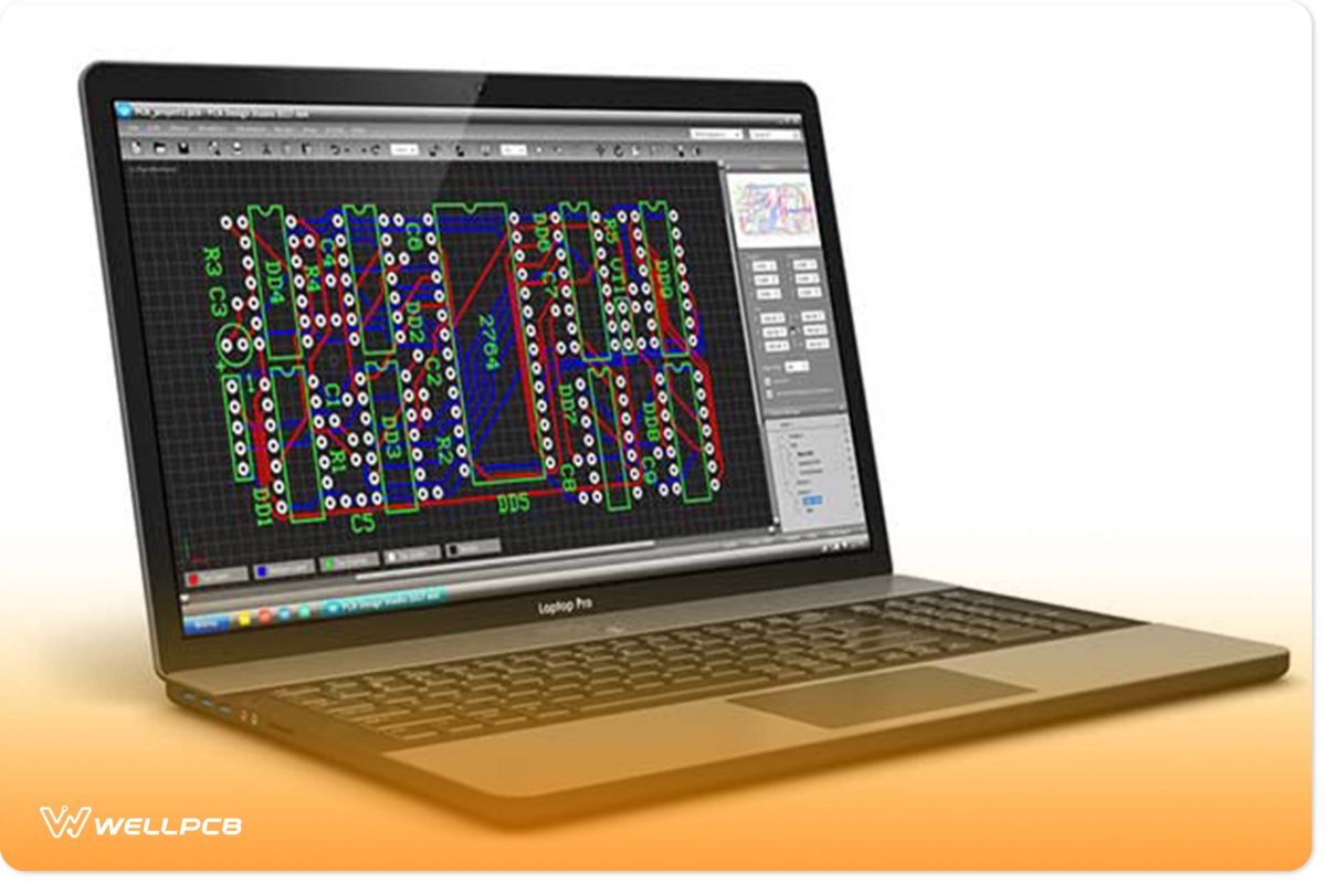
Figure 1 demonstrates a PCB file opened on a laptop. Your manufacturer will ask for this file to manufacture your circuit design. This file will tell them about your desired PCB dimensions, solder mask, finished copper, via the process, and other details.
PCB file formats
At this point, it is worth mentioning that your end file will not always have the .pcb file extension. It can be a Gerber file or a PCB file. Moreover, each software will have its specific file type. Rest assured, you will come across .pcb files more often.
Table I PCB File Formats
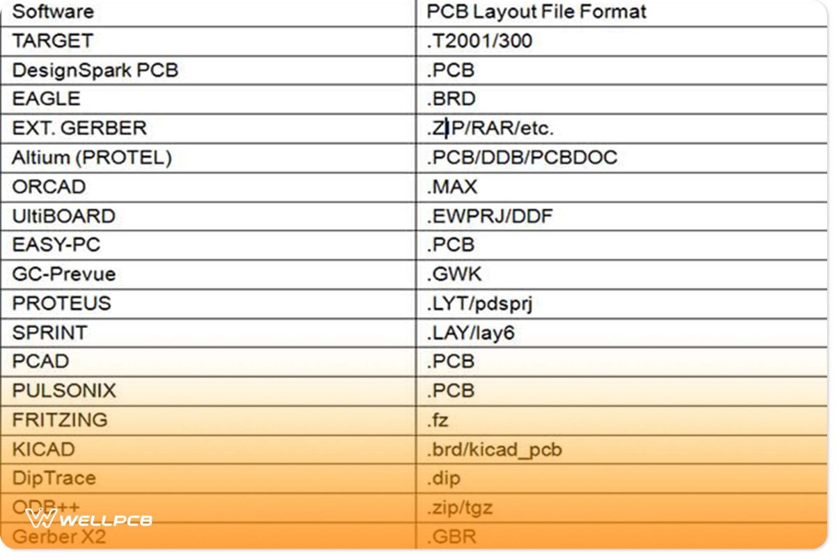
Which file format can I generate or export with common software?
In the business of PCB manufacturing, you will often need to produce a Gerber file format. Gerber file contains information regarding 2-D artwork that tells the manufacturer about the position of the solder mask, copper, etc.
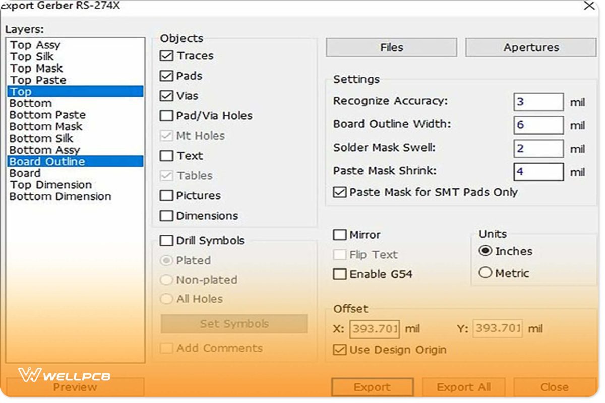
It will know nothing about net connectivity, design rules, or component libraries. So, you may find it hard to generate a Gerber file. You will need to contemplate different configuration details when producing a Gerber file.
Figure 2 demonstrates the options that you will encounter for producing Gerber files with DipTrace software.
In general, you can follow the following two steps for generating a Gerber file:
1. Look for a manufacturer who will provide you with instructions for generating a Gerber file. The instructions will be according to specific CAD software.
2. Then, you can use that CAD tool to design your printed circuit board.
However, this is not as easy as it sounds. Still, with practice, you can master this work. Further, you can avoid a non-functional PCB and delayed manufacturing by carefully following the instructions.
In this section, we introduced different PCB file formats and their generation. In the next section, we will tell you about opening them in Eagle and PCB file viewer.
How Do I Open a PCB File in Eagle and PCB File Viewer?
Opening a PCB file in Eagle
Eagle is undoubtedly one of the favorite software of an electronics engineer. It is a PCB design software and has made the designing process a pleasure. Now, a question may arise in your mind regarding opening a .pcb file in Eagle. Like, is it possible to open a .pcb file in Eagle?
Before we answer, we would like to know what you are thinking. Do you think it is possible? Recall the file format mentioned in Table 1, supported by Eagle. Unfortunately, the .pcb file format is not linked with Eagle. So, you cannot open a .pcb file with it, but you sure can use other software to do so.
Moreover, you can discover a user script here that can convert your file into something that Eagle can open.

Reviewing the PCB file in the PCB file viewer
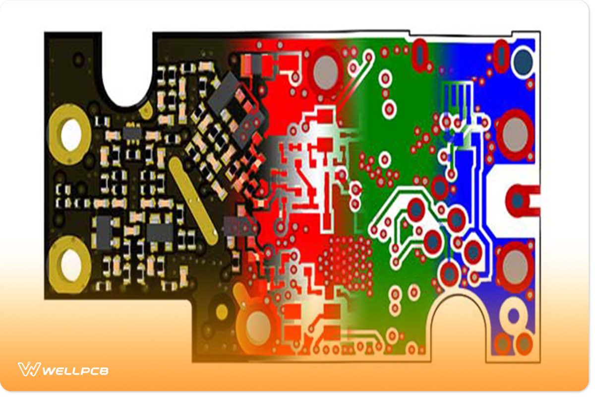
Once you have your desired .pcb file, you need to view it. Viewing it is crucial to make sure that it has everything that you and your manufacturer want. You can review your PCB files in a Gerber viewer. It will ensure that whatever you are submitting is an exemplary illustration of your design files.
Furthermore, previewing the .pcb files will also make sure that your files have been exported correctly. Figure 4 shows an illustration of Gerber files.
In this section, we told you about the importance of viewing your PCB file and how to open it in Eagle. In the next area, we will notify you about how to open them in different software.
How To Open or Convert Your PCB Files From Different Software
Eagle to Gerber
First of all, you will need to open your PCB design file in Eagle. This file will have a .brd extension. After that, follow the following instructions:
1. Select “File -> CAM Processor”. The CAM processor tool will open to produce your Gerber file.
2. Then, Select “File -> Open -> Job”.
3. Then go to your default cam folder of Eagle and select “gerb274x.cam -> Open”.
4. Finally, choose the “Process Job” button to generate the Gerber files.
For more information and the conversion about producing Gerber files, please see this article: Hands-On The Gerber File.
Altium to Eagle
You need to export your Altium design file into ACCEL ASCII file format. Luckily, you can import Altium files in Eagle. Eagle then imports this data structure. You will need to click on Import/File/Pad in Eagle and then follow the instructions.
Converting Gerber Files (“.gbr”) to “.pcb” files
You will need to change the file extensions for converting Gerber files (.gbr) to Altium (.pcb) files. For example, if you have a top layer Gerber file named “Layer1. Pho”, you can convert it into an Altium file by changing its name to “Layer1.GTL. “GTL” file extension refers to Gerber Top Layer.
You can visit the Altium (Protel) website to learn more about different file extensions.

PCB File Requirements
Every PCB manufacturer has some requirements which you need to fulfill before placing an order. The PCBs file that you will provide them must have these requirements.
PCB Design Requirements
According to some manufacturers, Gerber files should include:
- Drill Tool List
- Excellon Drill Files
- Inner layers with polarities depending upon the design
- Copper Layers
- Soldermask
- Silkscreen
- Aperture / D-Code List
- Readme file
- Board Outline
- Copper weight and dielectric thickness requirements
You will also come across a few manufacturers who will accept native design files of:
- Altium (Protel)
- EAGLE
- Ultiboard
- OrCAD
- PCB123
- IVEX
PCB Drill File Requirements
Again, the manufacturers will ask you to submit PCB drill files in the following way:
- Maybe in Excel format.
- They should not have “G01”, “G54” and “D” ciphers if opened in a text editor.
- They should not contain any weird graphical characters; they must have viewable ASCII text.
- If they are formatted correctly, they will have sizes parted with “T” ciphers.
- There should be a tool report containing the drill sizes.
- Give them an NC Drill File or a fab drawing for cutouts and slots.
- For a plated cutout or slot, you should put the attribute on the drill layer. After that, mention an outer layer pad having a minimum size of cutout or slot you want to be plated.
- For non-plated cutouts or slots, place them on the outline layer.
Circuit Board Routing Requirements
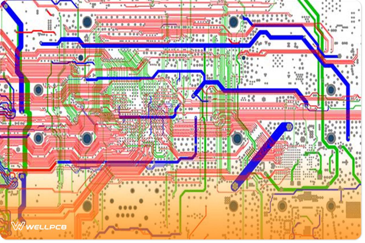
Manufacturers usually get the idea about circuit board routing from the PCB outline. Figure 5 shows the printed circuit board layout routing.
You should keep in mind the following points when submitting your PCBs file:
- During the routing process, we will recommend you use a copper backset of 0.020″. It will help you avoid damage to copper attributes.
- Some manufacturers may also allow you odd or round shapes, but with some constraints.
So, once you have fulfilled all the above and other similar requirements, you are all set to place an order. Exact requirements will depend upon your manufacturers. Just make sure to include everything in your .pcb file.
Conclusion
A PCB file is an essential thing that you should have for manufacturing your circuit design. This article discussed the details related to a file.
What are the PCB files? And What are its requirements? What kinds of PCB file formats are supported by different software? Why view it? How to convert or generate them?
You should always make sure that your PCB files are fulfilling all the requirements of your manufacturer. We are here to help you if you need any further assistance. Don’t hesitate to contact us today.
We never get tired of listening to our customers. Our team of Engineers will be glad to help you out in any way.


