Contents
THT vs. SMD: Definition

Fig 1: Technological process of soldering and assembly chip components on PCB board
Through-Hole Mounting Technology (THT)
THT is the original and popular assembly process that dominated the market until the 1980s. It’s a technology by which one places component leads into drilled holes on a bare PCB. Many professionals anticipated that the introduction and rise of the surface mount technology would sideline the THT. However, almost four decades later, the THT keeps on delivering, especially regarding reliability.
Through-hole components are ideally suited for high-reliability applications that necessitate stronger interlayer connections. Unlike SMT components, which employ solder on the board’s surface, the through-hole component leads through the board. It allows the components to resist higher environmental stress. Consequently, through-hole technology works well in military and aerospace equipment where intense accelerations, shocks, or extreme heat is common.
Surface Mount Technology (SMT)

Fig 2: A printed circuit board
SMT is a process of mounting components directly onto the surface of the printed circuit board (PCB). The process was developed in the 1960s and achieved immense popularity in the 1980s. Today, it is the most popular mounting technique, with virtually all electronic hardware using SMT.
It has become indispensable in PCB design and production, improving overall PCB quality and functionality while significantly lowering processing and handling costs.
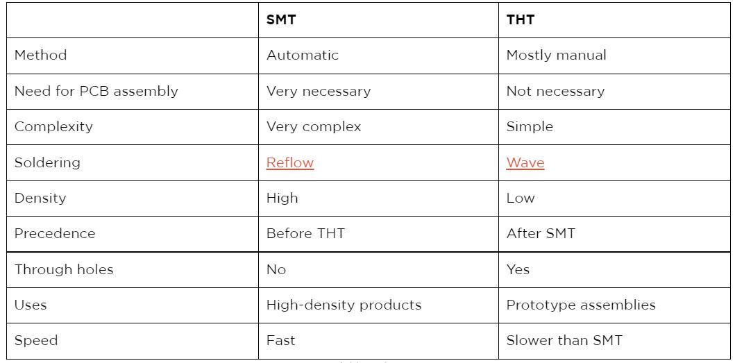
The main distinctions between SMT and through-hole mounting are:
- SMT does not require holes drilled through a PCB.
- SMT components are substantially smaller.
- You may put SMT components on both sides of the board.
Because of the capacity to place many tiny components on a PCB, PCBs have become significantly denser, higher performing, and smaller.

THT vs. SMD: Advantages and Disadvantages

Fig 3: PCB Processing on a machine working in a factory.
THT
Advantages
- THT has strong mechanical bonds, making it suitable for applications in high electrical or mechanical stress environments.
- THT components are robust and can withstand normal wear and tear.
- The technology is ideal for scenarios that need faster prototyping.
Disadvantages
- THT utilizes holes whose printing raises the production costs significantly.
- Second, THT has a low routing clearance on circuits composed of several layers.
- Thirdly, the wave soldering process used in soldering THT components falls short compared to the reflow soldering process.
SMD
Advantages
- Allows manufacturers to mount more electronic components on a circuit board.
- Next, SMD has better mechanical characteristics and is excellent for applications in zones with high vibrations.
- The smaller size of SMD electronic components allows for higher board densities.
- Also, SMD technology utilizes pick-and-place machines for quicker circuit board assembly.
- They’re less costly to manufacture
Disadvantages
- SMD uses small leads, which can be difficult to repair
- The technology doesn’t suit applications that generate too much heat.
- Also, SMD technology requires expensive automated equipment and highly-trained professional operators.
- The little solder technique may lower the reliability of these solder joints.
SMT vs. SMD

Fig 4: Electronic components on a PCB
SMT and SMD are two closely related but different terms used in PCB assembly. Also, SMT is a PCB assembly technology, while SMDs are SMT-mounted PCB components.
An SMD is short for a surface-mounted device. They are electronic components chosen and put on PCBs during SMT manufacturing. We have passive and active SMDS.
Passive SMDs are electronic components on a circuit board that don’t use or convert electrical energy to other forms. Examples include inductors, capacitors, couplers, and antennas.
Active SMDs are electronic circuit board components that use or convert electrical energy to other forms. Examples include rectifiers, triodes, valves, and transistors.
Conclusion
Today, we’ve seen the differences between THT, SMT, and SMD technologies and which one may suit you. As much as THT is an older process, we still use it when we have plug needs. On the other hand, SMT is more popular and is the technology you’ll find with most PCB assemblies.
Finally, contact us for more clarification or if you have questions, comments, or suggestions.


