Contents
What Is a Transistor
A transistor is a three-layer active component that switches or amplifies electrical signals in an IC. Additionally, an active component means its input voltage is greater than the output voltage.
Since transistors take less space and have better thermal resistance, transistors are a replacement for vacuum tubes. And transistors use lesser operational power.

transistors
Transistor Tree Diagram
Types of Transistors
Bipolar junction transistors
A Bipolar Junction Transistor (BJT) has three sections, namely, the emitter(E), base(B), and collector(C). Current flow from the base terminal outputs at a higher value at the collector and emitter terminals.
They use holes and electrons for electrical conductivities, hence “bipolar.” Consequently, the name junction is because they have two PN junctions.
Furthermore, BJTs have a low voltage input impedance, so they are the best for signal amplification.
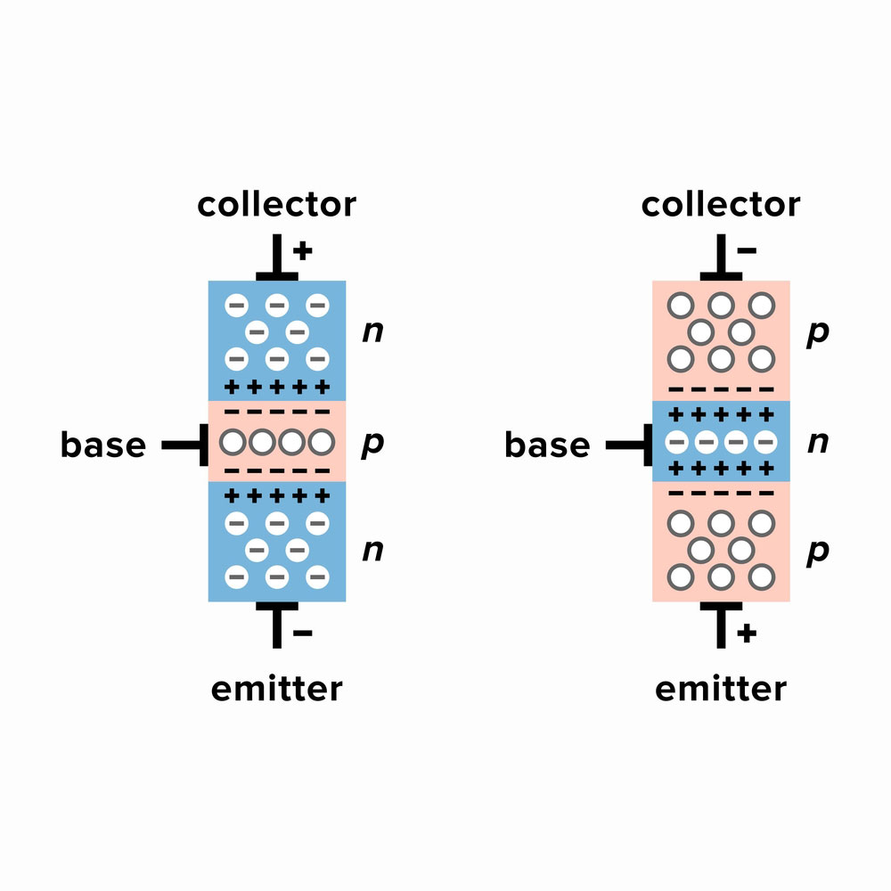
BJT operation
NPN Transistor
An NPN transistor consists of a p-type semiconductor between two n-type semiconductors. In this setup, holes are the minority charge carriers, while electrons are the majority carriers.
Accordingly, these transistors are preferable because of their higher electron mobility and low hole mobilities.
Notably, the electron mobility is from the emitter terminal to the collector terminal. Then, the emitter sends electrons to the base region as the base controls these emissions.
NPN transistor circuit diagram
PNP Transistor
A PNP transistor has two p-type semiconductors that sandwich a thinner n-type semiconductor.
Interestingly, the base-emitter junction still controls the current direction. However, it does that in the opposite direction of an n-type transistor.
PNP transistor circuit
Field Effect Transistor (FET)
A FET is a semiconductor device with three regions, namely, source(S), gate(G), and drain(D).
Moreover, it is a unipolar device since it uses only most carriers for electron mobility, unlike BJTs.
The voltage at the gate terminal controls the voltage source, thus determining the voltage to the drain terminal.
FETs have a high input impedance; thus, few electric currents run through them.
Furthermore, they are advantageous since they are cheaper and easy to produce.
Unfortunately, their output current amplification is not as efficient as BJTs.
Junction-Field Effect Transistor (JFET)
A Junction-Field Effect Transistor is an early form of FET that can act as a transistor switch or amplifier.
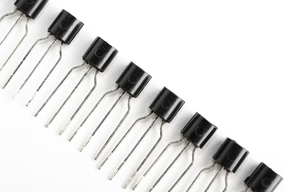
JFET transistors
MOSFET
A Metal Oxide Semiconductor Field Effect Transistor has a thin layer of metal oxide separating the channel and gate region.
Consequently, the oxide layer enables electricity to penetrate the silicon wafer it sits on. Specifically, the fabrication process is known as surface passivation.
Transistors Based on Function
Alternatively, transistor type classification is also done depending on how they work and the purpose they serve.
Small Signal Transistor
These work in a digital circuit to amplify low-level signals; however, they can also work as a switching transistor. And they are available in NPN and PNP formats with an hFE value between 0 and 100.
Additionally, they work best with a collector current of 80 to 600mA and a 1 to 300MHz frequency range.
Small Switching Transistors
Small switching transistors’ primary use is Switching, although they can also amplify electrical signals.
Also, they have hFE values of 10 to 200 but work better at switching than amplifying at the maximum rating.
Power Transistors
Power transistors work in high power circuits and hence have a power sink to prevent overheating. Besides, their ideal working power value ranges from 0 to 100W with a suitable frequency of 1 to 100 MHz
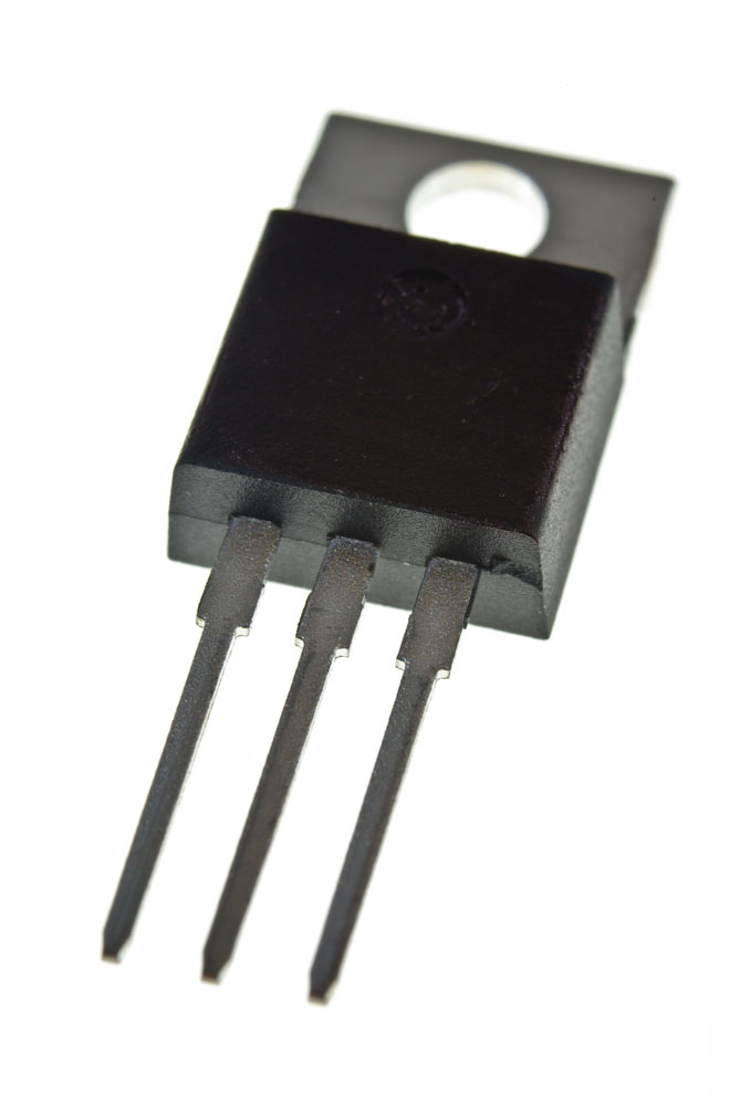
power transistor
High-Frequency Transistors
Also known as RF transistors, they work in high-speed switching applications. Moreover, they operate with a small input signal that functions at high frequencies.
Significantly, they have a collector current of 10 to 600 mA and a maximum 200 MHz frequency rating.
Photo Transistor
These are light-sensitive transistors. The photosensitive property replaces the base terminal, meaning the transistor is OFF when there is no light.
Furthermore, they are available as Photo-FETs and photo-BJTs. However, photo-BJTs are more sensitive to light.
NPN and PNP phototransistor circuit representation
Uni-Junction Transistors (UJT)
UJTs have three terminals, with two being the base and the other being the emitter. They work in switching operations and are not suitable for amplifying.
UJT circuit symbol
Heterojunction Bipolar Transistor (HBT)
An HBT is a bipolar transistor with different semiconductor materials at the emitter and base region, forming a heterojunction.
They are an upgrade from BJTs since they handle high-frequency signals and thus efficiently work in digital electronics.
Darlington Transistor
A Darlington transistor is a circuit combination of two bipolar transistors, increasing their current gain.
The emitter of one BJT connects to the base region of the other BJT. Also, they come in single transistor packages.
Schottky Transistor
It is a combination of a Schottky diode and a transistor. Moreover, the diode prevents transistor saturation from the current source by diverting excess current.
Multiple-Emitter Transistor
It is a special BJT primarily present at the inputs of ICs, logic gates, and NAND gates.
They replace diodes in DTLs, facilitating fast single transistor operations in logic gates. Additionally, its configuration reduces a circuit’s power dissipation.
Dual Gate MOSFET
It is essential in applications that require a dual gate in series. The gates impact the current flow level between the gate and the source terminal.
Avalanche Transistor
It is a BJT that operates in the avalanche breakdown region. It has less than nanosecond transition times and can switch extremely high currents.
Diffusion Transistor
It is a BJT with doping agents in the semiconductor material. However, the process of introducing dopants is carried out after the alloying and growth junction fabrication process of the BJT.
Additionally, here is a video illustration of how transistors work in a circuit.
How to Test Transistors?
You can test for damage or working condition of transistors by:
Use a multimeter
It can be a digital multimeter set to diode test or an analog multimeter set at a low resistance range.
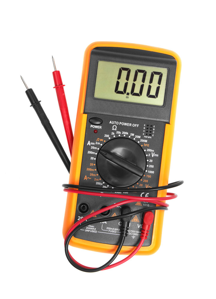
multimeter
Remember to test all leads both ways and check that:
The base-emitter junction and Base collector conduct in one direction like a diode.
Also, the collector-emitter junction should not conduct.
Using a simple circuit
- Include the transistor in a circuit.
- Also, remember to incorporate a 10k resistor at the base to protect the transistor.
- Ensure the supply voltage ranges between 5 and 12V.
- Therefore, if the transistor works, the LED should light when you engage the switch.
- Alternatively, reverse the same circuit and supply voltage for testing a PNP transistor.
Simple switching circuit
Conclusion
Hopefully, you are now familiar with all transistor types and how they work. If you need any clarifications or have questions, don’t hesitate to reach out to us.
